
Apparatus and method for determining density, porosity and fluid saturation of formations penetrated by a borehole

a technology of applied in the field of apparatus and method for determining density, porosity and fluid saturation of formations penetrated by boreholes, can solve the problems of inability to make quantitative density logs in boreholes, inability to distinguish between low porosity formations and formations, and inability to use logging tools as gas indicators

Inactive Publication Date: 2005-08-30
PRECISION ENERGY SERVICES
View PDF1 Cites 36 Cited by
  • Summary
  • Abstract
  • Description
  • Claims
  • Application Information

AI Technical Summary

Benefits of technology

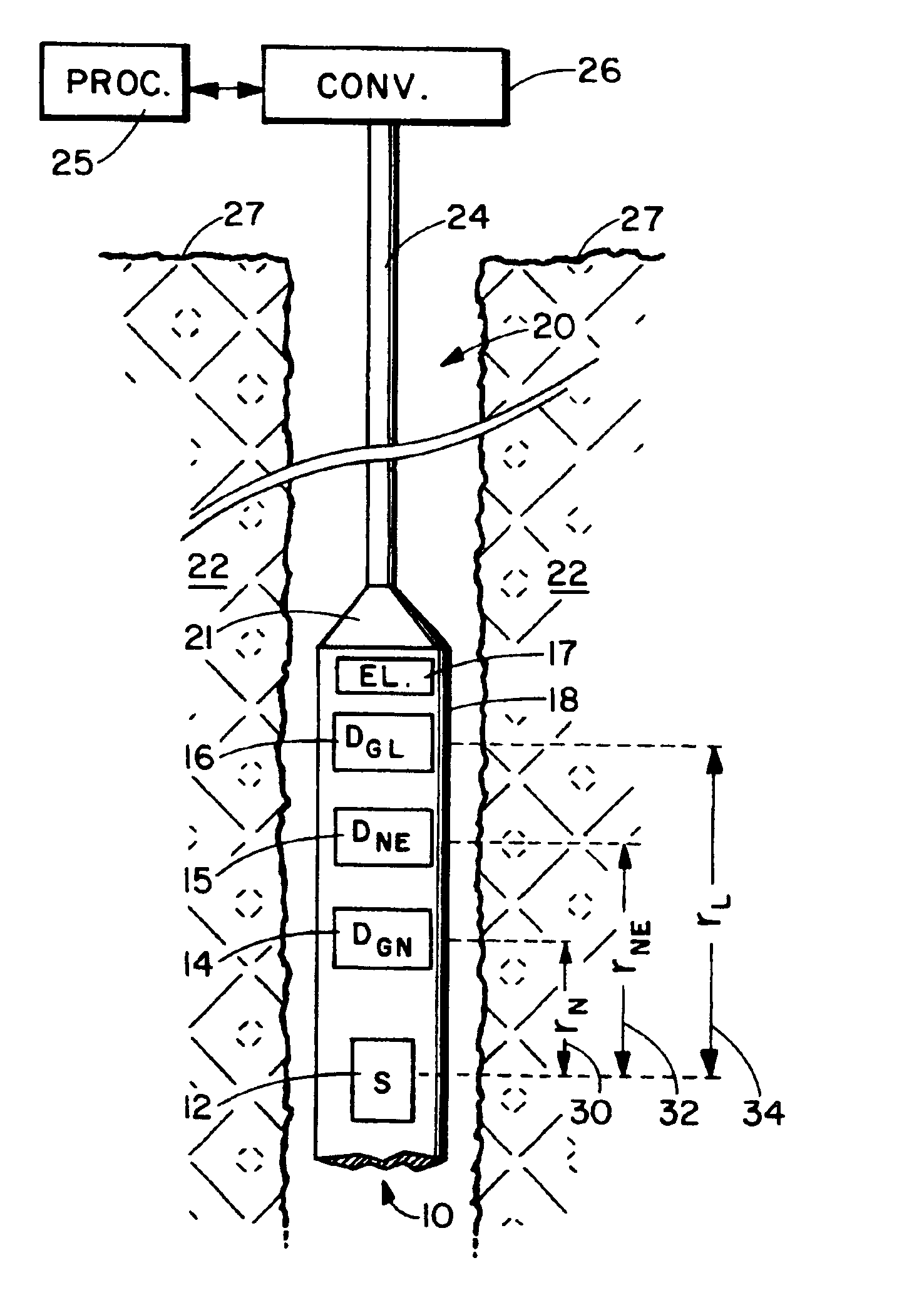
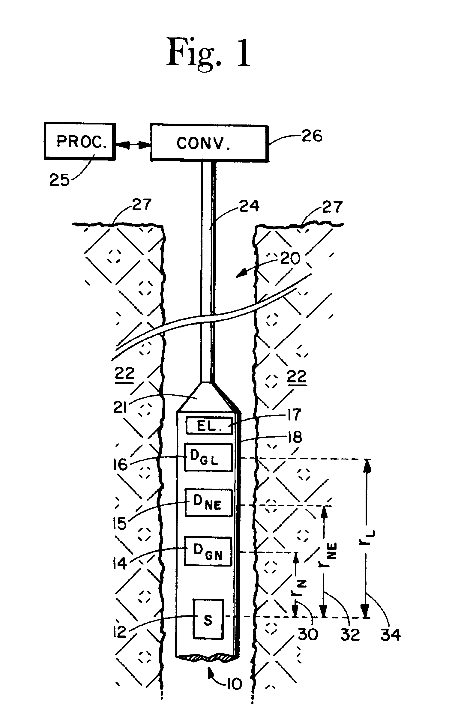
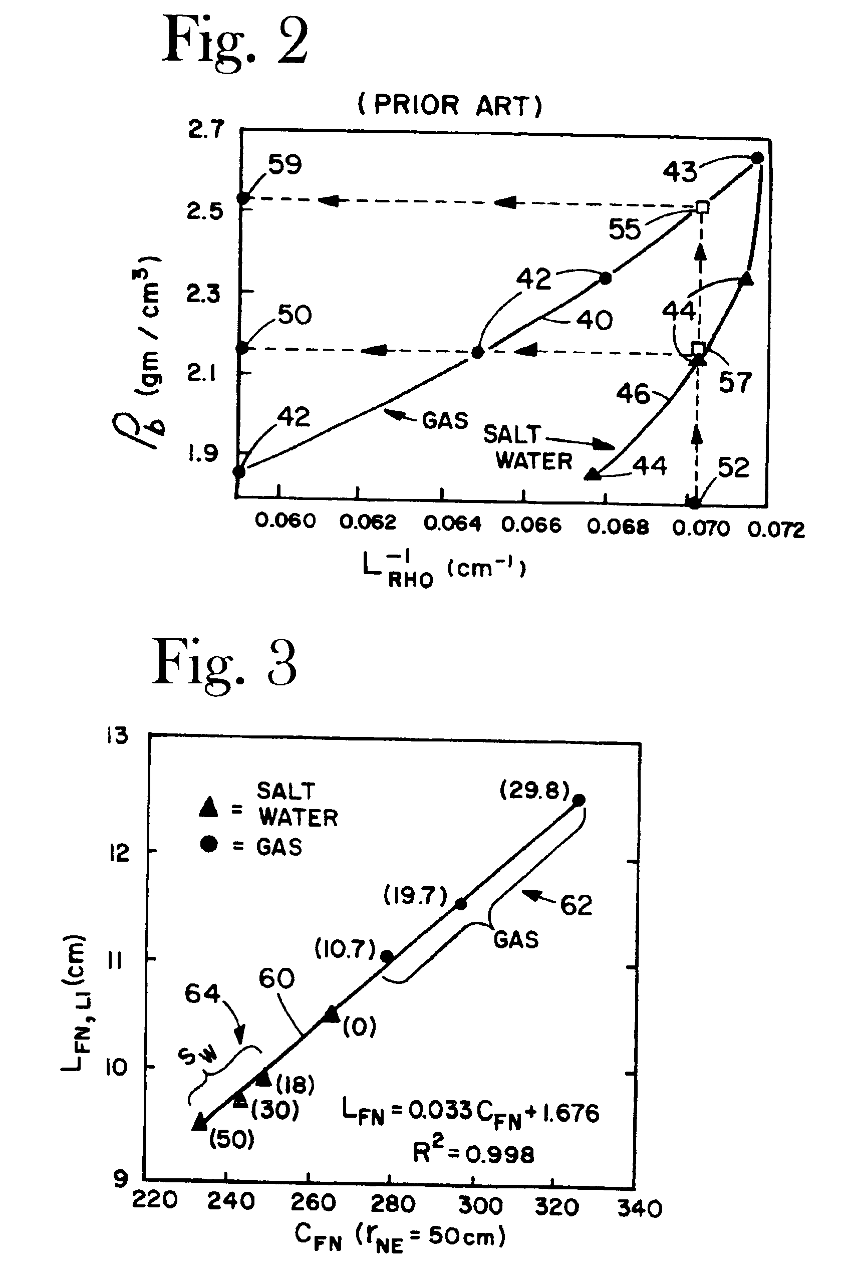
[0017]Attention is next directed toward the model that has been developed to process measured data. It is first noted that measured gamma radiation is generated within the borehole environs by fast neutron reactions. The gamma ray source is therefore dispersed rather than a point source assumed in many prior art systems. The model takes into account the dispersed nature of the inelastic gamma source, and is based on two-group diffusion theory. Group one describes the fast neutron transport from the logging tool into the borehole environs, and group two describes the inelastic gamma radiation transport within the borehole environs wherein a portion reaches the gamma ray detectors in the logging tool. The diffusion solution for the fast neutron group one becomes the source of inelastic scatter gamma radiation for group two. The diffusion length LFN characterizes the spatial distribution of fast neutrons. The diffusion solution for the inelastic gamma group describes the inelastic scatter gamma ray distribution, and contains terms dependent on the fast neutron diffusion length LFN and an inelastic scatter gamma ray diffusion length LIG. The solutions are analogous to the two-group neutron solutions developed in the previously referenced paper by Allen et. al. The solutions are for a uniform medium and with spherical geometry. In principle, LFN is computed from the model using fast neutron count rates measured at two or more suitable spacings from the neutron source. These count rates are proportional to the fast neutron flux. The inelastic gamma radiation flux is obtained from a convolution integral for a spherically symmetric source distribution. LIG is determined using LFN and inelastic scatter gamma radiation count rates measured at two different axial spacings from the neutron source. An iterative method using trial values of LIG quickly produces a solution in the form of an “linearized” diffusion length value, LIG,l. The iterative solution eliminates previously discussed ambiguities in liquid and gas saturated formations by producing a unique LIG,l for each formation bulk density value.
[0019]The present invention exhibits many advantages over prior art systems. Ambiguities in measurements in liquid and gas saturated formations are eliminated. The two-group diffusion model used as a basis for data analysis includes a distributed source of gamma radiation, which physically more closely represents the gamma ray measurements rather than a point source gamma ray source. Fast neutron diffusion length is measured with a single neutron detector, which is axially spaced a relatively large distance from the neutron source thereby minimizing adverse effects of the near borehole region, yet responding with statistically significant count rates for a given neutron source strength. Formation density, formation porosity, and formation fluid saturation are uniquely determined. The measurement can be made in both open and cased boreholes. The system can be embodied in a variety of borehole systems including a wireline logging system, a logging while drilling system, a coiled tubing logging system, and a slickline logging system. The neutron generator can be disabled when the tool is removed from the borehole thereby reducing the risk of radiation exposure to personnel and property. Other advantages will become apparent in the following detailed description of the preferred embodiments of the invention.

Problems solved by technology

This tool cannot make quantitative density logs in boreholes that have been cased, where the casing is typically steel and is surrounded by a cement sheath.
Although operable in cased boreholes where previously discussed gamma-gamma density systems are insensitive, the LRHO system yields ambiguous results in formations saturated with liquid and saturated with a gas / liquid fluid mixture.
However, when a formation zone is encountered where the pore water is replaced by gas, the porosity tool gives an erroneously low porosity indication, while the density tool correctly indicates a decrease in bulk density with corresponding apparent increase in porosity.
This method is problematic in cased boreholes because of the more shallow investigation depth of the density log and its resulting greater sensitivity to variations in borehole conditions, such as variations in the thickness of the cement sheath, immediately behind the casing.
However, the cross section is not very sensitive to the presence of gas, and therefore the logging tool is not very useful as a gas indicator.
For this reason, the gamma ratio response, like the neutron-neutron porosity tool response, is not capable of distinguishing between low porosity formations and formations with higher porosity whose pore spaces are gas filled.
There is no teaching of methods to resolve ambiguities in density measurements for formations saturated with liquid and formations saturated with a significant fraction of gas.
Although the system does minimize ambiguity in liquid and gas filled formations, there are still deficiencies in the methodology.
The axial spacing of the neutron detector from the source is not optimized to minimize adverse borehole effects because of count rate statistics limitations.
This methodology essentially assumes a point gamma radiation source, which physically is not robust as will be discussed in subsequent sections of this disclosure.

Method used


Image

  • Apparatus and method for determining density, porosity and fluid saturation of formations penetrated by a borehole
  • Apparatus and method for determining density, porosity and fluid saturation of formations penetrated by a borehole
  • Apparatus and method for determining density, porosity and fluid saturation of formations penetrated by a borehole

Examples


Embodiment Construction

[0029]The invention set forth in this disclosure is embodied as a logging system to measure density, porosity and gas / liquid fluid saturation in earth formations penetrated by a cased or open borehole. As mentioned previously, gas / liquid fluid saturation is typically expressed as liquid saturation SW, or alternately as gas saturation SG, where SG=(1−SW). Prior to disclosing features of the model and the data processing methodology, a brief discussion of concepts underlying the measurements are appropriate.

3. Basic Concepts of the System

[0030]At least one of the measured count rates is proportional to fast neutron flux present during the sequential neutron bursts. Another measured count rate is proportional to prompt gamma radiation due to the inelastic scattering of fast neutrons off of formation and borehole nuclei during each neutron burst. Both of these measurements derive from nuclear interaction processes of neutrons in the MeV range with the nuclei and electrons of atoms compr...


PUM


Abstract

A borehole logging system for determining bulk density, porosity and formation gas / liquid fluid saturation of formation penetrated by a borehole. Measures of fast neutron radiation and inelastic scatter gamma radiation, induced by a pulsed neutron source, are combined with an iterative numerical solution of a two-group diffusion model to obtain the formation parameters of interest. Double-valued ambiguities in prior art measurements are removed by using the iterative solution of the inverted two-group diffusion model. The system requires two gamma ray detectors at different axial spacings from the source, and a single neutron detector axially spaced between the two gamma ray detectors. The system can be embodied as a wireline system or as a logging-while-drilling system.

Description

[0001]This is a continuation of application Ser. No. 10 / 104,449 filed on Mar. 19, 2002 now abandoned.BACKGROUND OF THE INVENTION[0002]1. Field of the Invention[0003]This invention is directed toward logging of earth formations penetrated by a borehole, and more particularly directed toward the determination of formation density, formation porosity and formation fluid saturation from measures of fast neutron and inelastic scatter gamma radiation induced by a pulsed source of fast neutrons. A two-group diffusion model is employed which defines a distributed source of gamma radiation within the formation resulting from fast neutrons impinging upon and inelastically scattering from nuclei within the formation. Ambiguities in prior art measurements are removed by using iterative solutions of the inverted two-group diffusion model.[0004]2. Background of the Art[0005]Density logging systems, which are compensated somewhat for the effects of the borehole, were introduced in the mid 1960s in...

Claims


Application Information

Patent Timeline
IPC IPC(8): G01V5/08G01V5/10G01V5/00
CPCG01V5/104
Inventor ODOM, RICHARD C.TILLER, DONALD E.WILSON, ROBERT D.
Owner PRECISION ENERGY SERVICES
Learn More