
Method and apparatus to detect and locate roof leaks

a technology for roof leaks and methods, applied in the direction of roof coverings, electrical testing, instruments, etc., can solve the problems of premature roof failure, failure to detect, find and correct, and costly roofing problems, so as to reduce measurement ambiguity and increase fault locating sensitivity

Active Publication Date: 2012-11-27
DETEC SYST
View PDF14 Cites 64 Cited by
  • Summary
  • Abstract
  • Description
  • Claims
  • Application Information

AI Technical Summary

Benefits of technology

"The present invention provides a method for locating defects in a water impermeable membrane of a roof by using a grid of conductive detectors placed on the membrane. The detectors are insulated from each other and a shielding conductor is used to reduce stray leakage current. The method involves measuring the electrical potential difference between the conductive detector and the roof deck, and using an electric potential difference between the conductive detector and the shielding conductor to create a sensing zone for detecting any defects in the membrane. The method can provide accurate results and is particularly useful for roofs with a high degree of moisture and can also be used with other types of roofs such as steel, concrete, and wood."

Problems solved by technology

The failure to detect, find and correct minor roof deterioration in the earliest stages is considered the greatest cause of premature roof failure.
Costly roofing problems are often the result of design deficiencies or faulty application of the roof system.
Even when properly designed and applied, all roofing materials deteriorate from exposure to the weather at rates determined largely by the kind of material and the conditions of exposure.
However several roof designs incorporate membranes that are directly adhered to the roof deck thereby limiting the placement and effectiveness of this type of moisture sensor application.
In some cases the leakage current from roof drains, un-insulated metal flashings and other roof fixtures can result in higher than normal current leakage to grounding points on the roof membrane.
This stray leakage current can be on the order of several milliamps and result in fault locating ambiguity in the area being tested.

Method used


Image

  • Method and apparatus to detect and locate roof leaks
  • Method and apparatus to detect and locate roof leaks
  • Method and apparatus to detect and locate roof leaks

Examples


Embodiment Construction

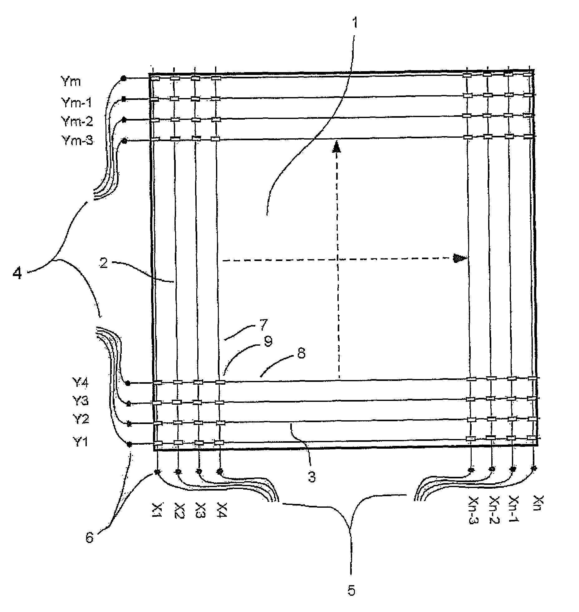
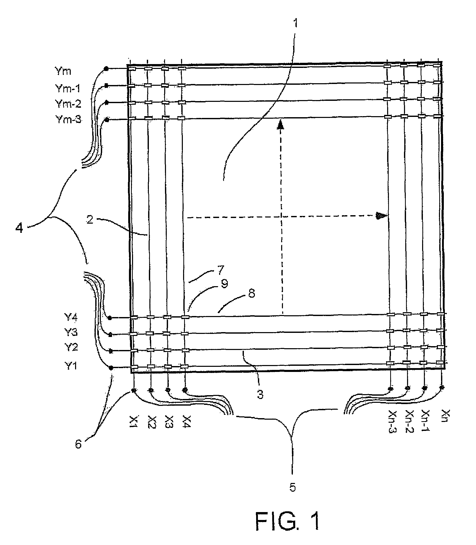
[0054]Referring now to FIGS. 1 to 5 of the drawings, the overall arrangement of the subject roof membrane moisture detection system can best be seen with reference to FIGS. 1 and 4. A roof membrane 1 is illustrated which is applied as a direct covering layer over a roof deck 1A. The deck is typically of concrete but can be of any suitable material to provide the necessary structural strength and can be steel or wood. The membrane is an impervious material such as plastics and is sealed at any joints to provide a continuous water barrier over the roof deck. This barrier is intended to provide the leak prevention and any penetration therein caused by a puncture or faulty seal or by wear can allow the moisture to penetrate to the deck where it can cause damage or can continue into the structure to cause damage to internal structures.

[0055]The membrane may be covered by a layer of an aggregate material for heat insulation and protection. If used, the aggregate may be loose or may contai...


PUM


Abstract

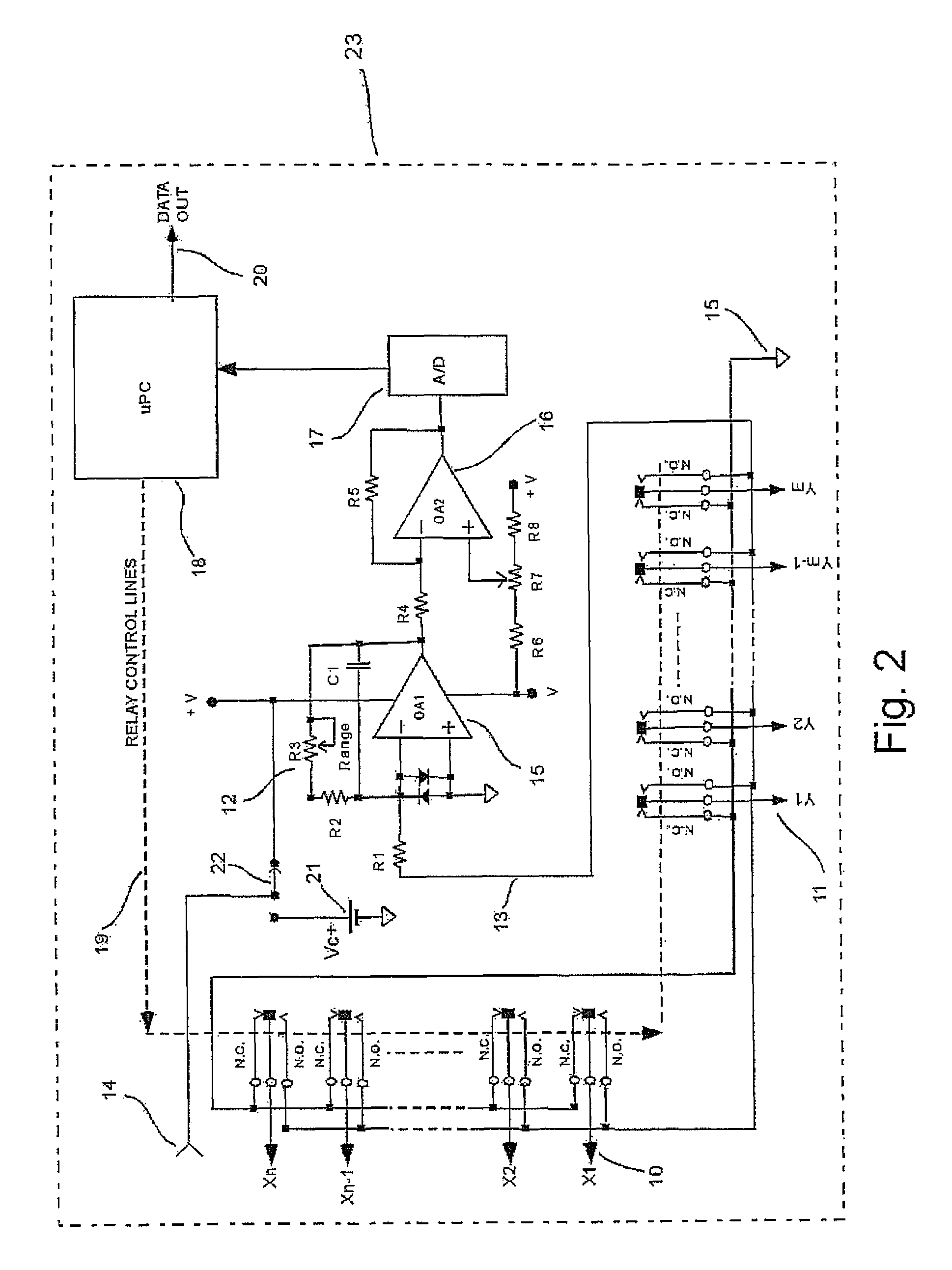
A leak in a membrane on top of a horizontal roof deck is located by applying conductive wires on the membrane underneath the aggregate in a grid pattern. A measuring and switching circuit generates voltage having a positive attached to the roof deck and a negative attached to the wires. The circuit has a relay for each wire which can be switched between a current sensor system and the negative potential. The sensor system is arranged to sense at each of the wires in turn the current flowing from the roof deck through any leak in the membrane to the wire. A micro-processor operates the relays in turn to connect all the other wires to the negative as a shield while each wire is sensed. From the output of the grid the changes in current in the x and y directions are analyzed to locate the leak in the membrane.

Description

[0001]This application is a continuation-in-part application from PCT Application No. PCT / CA2008 / 001457 filed Aug. 13, 2008.[0002]The present invention relates to a system for monitoring roof membranes for the presence and location of moisture penetration. It has particular application to monitoring low-slope and flat roofs of residential and commercial buildings for undesired water ingress.BACKGROUND OF THE INVENTION[0003]The failure to detect, find and correct minor roof deterioration in the earliest stages is considered the greatest cause of premature roof failure. This is particularly true of roofing materials applied on low-slope or flat roofs. Costly roofing problems are often the result of design deficiencies or faulty application of the roof system. Even when properly designed and applied, all roofing materials deteriorate from exposure to the weather at rates determined largely by the kind of material and the conditions of exposure.[0004]Several methods have been used to tr...

Claims


Application Information

Patent Timeline
Patent Type & Authority Patents(United States)
IPC IPC(8): G01R27/08G08B21/00G01R31/08
CPCC23F13/02E04D13/006G01D5/16G01D5/25G01M3/16
Inventor VOKEY, DAVID E.
Owner DETEC SYST
Learn More