
Graphite composites and methods of making such composites

a graphite and composite technology, applied in the field of graphite, can solve the problems of requiring significant effluent remediation, the above process cannot be used to control the amount of exfoliation, and the inability to produce nano-particle sized graphite flakes, so as to reduce the need for pollution abatement and reduce the cost of material

Inactive Publication Date: 2005-08-09
GRAFTECH INT HLDG INC
View PDF9 Cites 52 Cited by
  • Summary
  • Abstract
  • Description
  • Claims
  • Application Information

AI Technical Summary

Benefits of technology

[0013]One advantage of the invention is that the aforementioned methods may be used to manufacture graphite in a form that has a thickness of less than about 10 microns, preferably less than about 1 micron, more preferably less than about 100 nm, even more preferably less than about 10 nm, and most preferably less than about 1 nm. Also, the inventive methods may be used to increase the volume expansion of the graphite particle during processing as compared to the volume expansion resulting from the conventional intercalation-exfoliation process. The inventive methods may result in a volume expansion of an individual graphite particle of more than about 1000 times. It is believed that the volume expansion of a particle processed by the inventive methods is at least about a ten (10) fold increase as compared to the volume expansion of a particle treated with the conventional process.
[0014]Another advantage of the invention is that it includes a new method to process natural graphite into new forms of powdered graphite that have applications in supercapacitors, batteries, catalyst supports, and polymeric / graphitic composites.
[0015]Practicing the invention will result in the advantage of reducing, preferably eliminating, the production of the environmentally unfriendly sulfuric and / or nitric species during the intercalation process. Likewise practicing the invention may result in the advantage of reducing, preferably eliminating, the use of chemical compounds to treat the environmentally unfriendly sulfuric and / or nitric species produced during the intercalation process.
[0016]Another advantage of the invention, is that an aspect of the invention may be practiced to produce an exfoliated graphite flake that does not require the aforementioned heating of the intercalated graphite to a temperature of 700° C. to 1200° C. A further advantage of the invention is the invention may be practiced to produce a flexible graphite article that is substantially free of the aforementioned sulfuric species and / or nitric species. Furthermore, the advantages of the invention include that the invention enabled the use of an entirely new class of chemical compounds as intercalates than what was previously unavailable as an intercalant.
[0017]Additionally, practicing the invention will result in the advantage of being able to produce expanded graphite without having to practice traditional intercalation processes. The advantages of the invention also include the ability to recycle the fluid, resulting in the benefits of reducing the need for pollution abatement and reducing material costs.
[0018]A further advantage of the invention is that the invention may be practiced to separate adjacent graphene layers that do not have defects between the adjacent layers, or defects within the crystalline layer. Defects is used herein to describe irregularities in the structure of the graphite flake such as crystalline dislocations, atomic vacancies, fracture planes, polycrystalline grain boundaries, or other crystalline structure non-uniformities, as well as, impurities between the graphene layers, such as the presence of silicon, magnesium, potassium, sodium, aluminum, iron, or phosphorus elements in between the graphene layers.

Problems solved by technology

A drawback of the above intercalation process is that it requires significant remediation of effluents generated during the process.
Another drawback of the intercalation and exfoliation process is that the above process cannot be used to control the amount of exfoliation or to produce nano-particle sized graphite flakes.

Method used


Image

  • Graphite composites and methods of making such composites
  • Graphite composites and methods of making such composites

Examples


Embodiment Construction

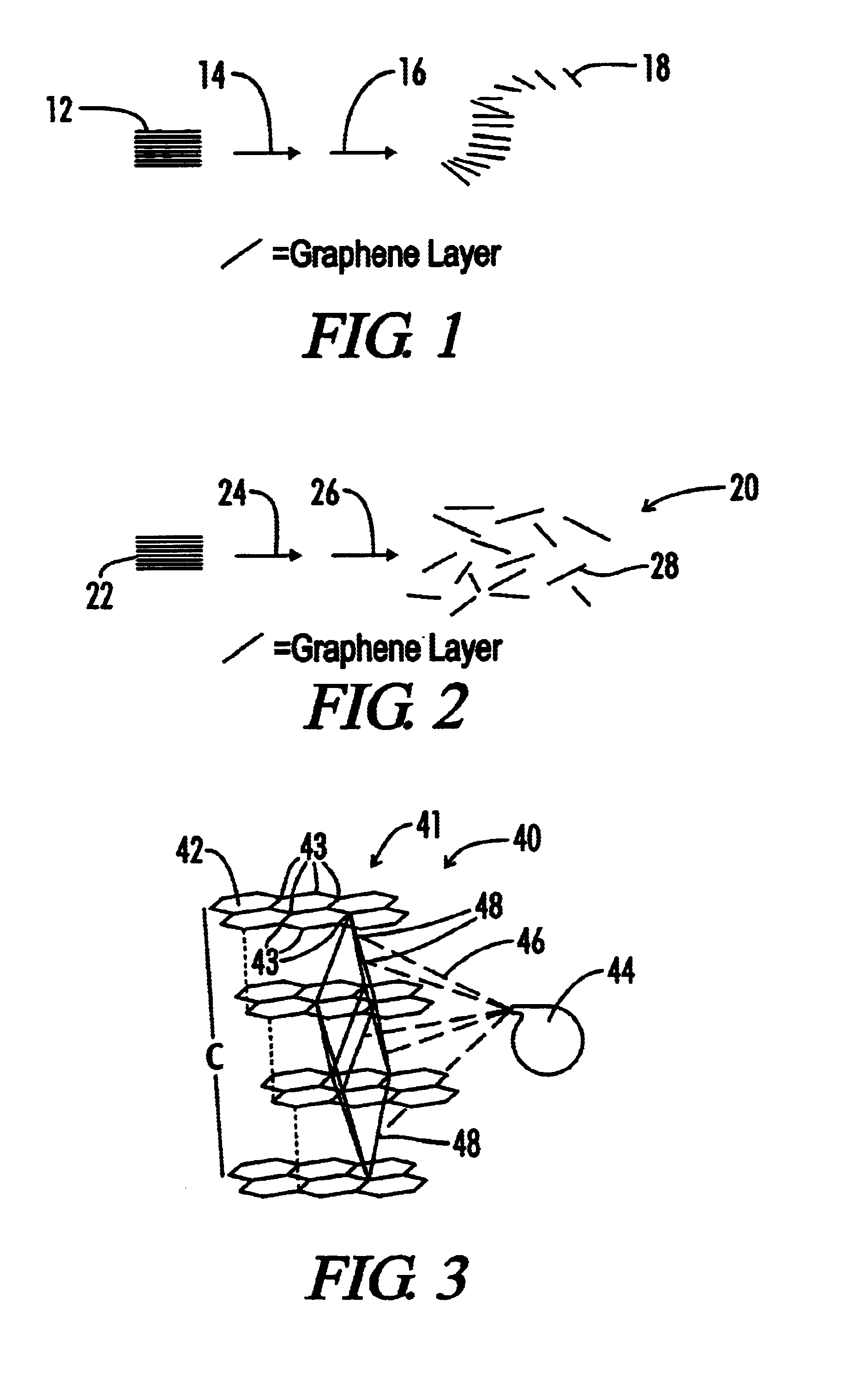
[0027]The invention will be further described in regards to the accompanying drawings. Whenever possible, like or the same reference numerals may be used to describe like or the same elements. Illustrated in FIG. 2 is a schematic diagram of one embodiment of a method to modify graphite in accordance with the invention, generally designated 20.

[0028]The method includes a step 24 of intercalating at least one flake of natural graphite 22 with an intercalant and optionally an oxidizing agent. In one embodiment, the natural graphite flakes are intercalated by dispersing the flakes in a solution containing a mixture of nitric acid (oxidizing agent) and sulfuric acid (intercalant). The intercalation solution may contain other acidic compounds and intercalating agents instead of or in addition to sulfuric acid. Examples of other acidic compounds include solutions containing organic acids, e.g., acetic acid, nitric acid, potassium chlorate, chromic acid, potassium permanganate, potassium ch...


PUM

PropertyMeasurementUnit
temperatureaaaaaaaaaa
thicknessaaaaaaaaaa
thicknessaaaaaaaaaa

Abstract

The invention may be practiced to make graphite composites. Preferred composites which may be made in accordance with the invention include conductive polymeric composites (thermally or electrically), paint composites, battery composites, capacitor composites, and pollution abatement catalyst support composites. One method of making the graphite aforementioned composites includes introducing an intercalant into at least one interstice of at least one flake of natural graphite. The method also includes introducing a fluid into the at least one interstices of the flake. Preferably, the fluid comprises at least one of a sub-critical fluid, near critical point fluid, or a supercritical fluid. Furthermore the method includes blending the flake with a polymer, thereby forming a graphite-polymeric composite.

Description

FIELD OF THE INVENTION[0001]This invention relates to graphite and more particularly to graphite-composites and methods of making such graphite composites.BACKGROUND OF THE INVENTION[0002]Graphites are made up of layered planes of hexagonal arrays or networks of carbon atoms. These layered planes of hexagonally arranged carbon atoms are substantially flat, covalently bonded in the flat layered planes, and are oriented or ordered so as to be substantially parallel and equidistant to one another. The substantially flat, parallel equidistant sheets or layers of carbon atoms, usually referred to as basal planes, are linked or bonded together and groups thereof are arranged in crystallites. Highly ordered graphites consist of crystallites of considerable size; the crystallites being highly aligned or oriented with respect to each other and having well ordered carbon layers. In other words, highly ordered graphites have a high degree of preferred crystallite orientation. It should be note...

Claims


Application Information

Patent Timeline
Patent Type & Authority Patents(United States)
IPC IPC(8): C08K3/04C08K3/00
CPCC08K3/04Y02P20/54
Inventor KASCHAK, DAVID M.REYNOLDS, III, ROBERT A.KRASSOWSKI, DANIEL W.
Owner GRAFTECH INT HLDG INC
Learn More