
Reflective lithography mask inspection tool based on achromatic Fresnel optics

a technology of achromatic fresnel optics and inspection tools, applied in the field of lithography, can solve the problems of replacement, maintenance, and high cost of initial tools, and achieves improved spatial resolution, high precision, and high resolution

Inactive Publication Date: 2005-07-05
XRADIA
View PDF12 Cites 50 Cited by
  • Summary
  • Abstract
  • Description
  • Claims
  • Application Information

AI Technical Summary

Benefits of technology

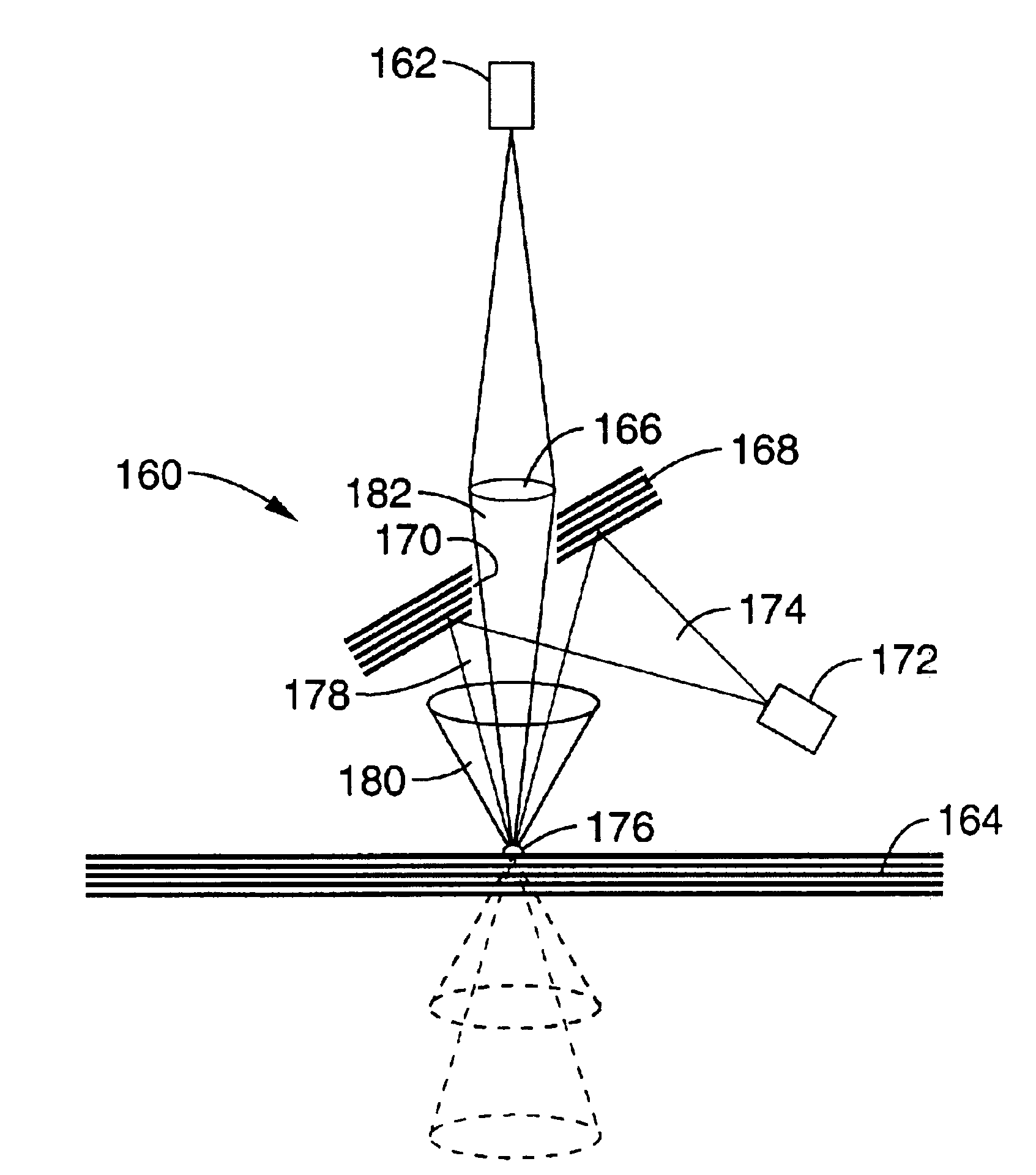
[0015]The disclosed method offers several major advantages. First, the imaging property of the AFO allows both the imaging of the structure of a patterned multilayer mask and the detection and imaging of defects on a multilayer mask blank. Since the operating wavelength of the AFO operates at or near the designed operating wavelength of the multilayers, the disclosed imaging system closely resembles the operation of the printing process. In such an actinic systems, only the relevant defects on a multilayer mask blank or only the printable structures on a patterned mask blank are imaged. It can be used in a bright field, dark field, or phase contrast imaging modes, similar to that a lens used in an optical microscope. Second, an AFO based imaging system can achieve a spatial resolution better than 25-nm, which has been demonstrated using zone plates at ˜500 eV x-rays. Therefore structures on a patterned multilayer mask can be imaged with high resolution and high precision, allowing further classification of defects on a multilayer mask blank or a multilayer patterned mask to help identify the root cause of failures. Third, an AFO based imaging system can have a high throughput since the AFO can have a numerical aperture greater than 0.2. Fourth, an AFO based imaging system will efficiently utilize the energy from a broad-spectrum source since it can be designed with a bandwidth of up to 1.5%. Fifth, an AFO based imaging system can be constructed with a field of view of many millimeters, permitting the imaging of the structure of a patterned mask over a large area or the detection of defects over a large area of a mask blank.

Problems solved by technology

Further reduction in wavelength using current refractive lens-based lithography methods can be extremely difficult and is limited by a lack of suitable materials for making the imaging lenses.
Because of the large number of multilayer mirrors must be used, only a small percentage of the EUV source power is delivered to the wafer, while a large amount flare is added to the exposure.
Consequently the costs of initial tool, replacement, and maintenance are extremely high.
Therefore, compound refractive lenses are not likely to be useful as objectives in the next generation lithography methods because they do not have the required numerical aperture with an acceptable system throughput.
This chromaticity precludes its application in lithographic imaging cameras since an illumination beam with an extremely narrow spectral bandwidth would be required to limit chromatic aberrations should a printing field of sufficient size be required.
This would consequently severely limit the energy from the source that can be used for exposing the photoresist.

Method used


Image

  • Reflective lithography mask inspection tool based on achromatic Fresnel optics
  • Reflective lithography mask inspection tool based on achromatic Fresnel optics
  • Reflective lithography mask inspection tool based on achromatic Fresnel optics

Examples


Embodiment Construction

[0040]The preferred embodiments of reflective lithography mask inspection tools based on an achromatic Fresnel objective, or AFO lens, according to the present invention will now be described, as will the AFO lens upon which such tools are based.

[0041]The inventive AFO lens combines a diffractive Fresnel zone plate and a refractive Fresnel lens. It will be appreciated that a Fresnel zone plate is a diffractive imaging optic comprising a set of concentric rings with the ring (zone) width decreasing with radius and that several research groups have demonstrated imaging at sub-30 nm resolution in the 2-5 nm wavelength range, which is the highest resolution demonstrated for the entire spectrum of electromagnetic radiation. A Fresnel zone plate is characterized by its radius R, the width of the outermost zone ΔR, and the number of zones N. The resolution of a zone plate according to the Rayleigh criteria is 1.22ΔR under appropriate illumination conditions. The imaging property of a zone ...


PUM


Abstract

A mask blank inspection tool includes an AFO having a diffractive lens and a refractive lens formed on a common substrate. The diffractive lens is a Fresnel zone plate and the refractive lens is a refractive Fresnel lens. The AFO is used to image light from a defect particle on a multilayer mask blank or the surface of the multilayer mask blank to a detector.

Description

CROSS-REFERENCE TO RELATED APPLICATIONS[0001]This application is a continuation-in-part of copending application Ser. No. 10 / 289,151 filed on Nov. 5, 2002, which is a continuation-in-part of copending U.S. application Ser. No. 10 / 134,026 filed on Apr. 25, 2002, incorporated herein by reference, which claims priority from U.S. provisional application Ser. No. 60 / 337,752 filed on Nov. 9, 2001, incorporated herein by reference, and from U.S. provisional application Ser. No. 60 / 338,362 filed on Nov. 9, 2001, incorporated herein by reference.[0002]This application is also continuation-in-part of copending application Ser. No. 10 / 134,026 filed on Apr. 25, 2002, incorporated herein by reference, which claims priority from U.S. provisional application Ser. No. 60 / 337,752 filed on Nov. 9, 2001, incorporated herein by reference, and from U.S. provisional application Ser. No. 60 / 338,362 filed on Nov. 9, 2001, incorporated herein by reference.[0003]This application also claims priority to U.S. ...

Claims


Application Information

Patent Timeline
IPC IPC(8): G02B27/42G02B3/08G03F7/20G02B27/44
CPCG01N21/956G03F1/84G02B27/4211G02B27/4272G02B3/08G01N2021/8822G01N2021/95676
Inventor YUN, WENBINGWANG, YUXIN
Owner XRADIA
Learn More