MEMS-based variable capacitor

a variable capacitor and capacitor technology, applied in the field of variable capacitors, can solve the problems of no means or mechanisms by which the desired capacitance value can be actively maintained or adjusted, prior variable capacitors are prone to drifting from the desired capacitance value, etc., and achieves low loss tangent, high k factor value, and easy operation

Active Publication Date: 2005-06-21
FOR NAT RES INITIATIVES
View PDF4 Cites 66 Cited by
  • Summary
  • Abstract
  • Description
  • Claims
  • Application Information

AI Technical Summary

Benefits of technology

[0015]It is, therefore, an object of the present invention to provide a variable capacitor that can be made on a commonly used substrate in the radio frequency technology domain called Low-Temperature Co-Fired Ceramics (“LTCC”), which has excellent high-frequency performance characteristics.
[0016]It is another object of the present invention to provide a variable capacitor device wherein the packaging of the device allows environmental protection of the component as well as low manufacturing cost.
[0017]It is a further object of the present invention to provide a variable capacitor device that has lower installation, assembly, tuning and maintenance costs.

Problems solved by technology

First, the prior variable capacitors are prone to drifting from the desired capacitance value to some other undesired capacitance value over time due to temperature or other environmental effects.
Second, prior variable capacitors have no capability for active tuning of the device capacitance before or during operational use.
This means that once the component value of capacitance has been adjusted on the factory floor, there is no means or mechanism by which the desired capacitance value can be actively maintained or adjusted.
Third, the process of tuning prior variable capacitor devices to a desired capacitance value is a manual operation usually involving a technician, and thus is time intensive and costly.
Fourth, the process for adjusting capacitors to a desired value is prone to error in a production line environment.
This error is typically detected in later stage testing and usually can be corrected by subsequent tuning adjustment; but this increases cost significantly.
Alternatively, the device out of specification can be scraped, but this is expensive as well.
Fifth, the prior technology of variable capacitors has a very limited tuning range.
This is primarily due to the fact that the mechanical movement is typically limited to a linear motion, and as a result, the tuning ratio (i.e., the ratio of minimum to maximum capacitance values over the entire dynamic range of the device) is generally limited to 10 to 1 or less.
The disadvantage of this is that a much larger number of different variable capacitor devices with a slightly different tuning range must be made in order to have capacitors adequately cover the entire range of possible continuous capacitance values.
Since almost any value of variable capacitance is desired in practical applications, the result is a significantly higher design and manufacturing costs, as well as high inventory costs, as would not be the case with a smaller number of variable capacitors with a larger dynamic range.
Sixth, the current versions of variable capacitors are large in size, and therefore, consume a larger amount of space on the mounting substrates, such as Printed Circuit Boards (PCBs), ceramic substrates, etc.
Seventh, the maximum operating frequency and the quality factors (Q) of the prior variable capacitors are somewhat limited.
This is a particular problem as RF systems using these components have steadily moved into higher operational frequency ranges and the performance demands for higher signal to noise ratio and lower power consumption have increased significantly.
However, it is expected that very little improvement in cost reduction will be made in manufacturing these components in the future.
Furthermore, despite the cost reduction achievements that have been made, these devices are still relatively expensive when compared to other components.
Moreover, as pointed out above, there is a substantial additional cost associated with installing and tuning these devices compared to other components.
While this approach works for the demonstration of a device, it presents several major disadvantages for the commercialization of discrete microwave or high-frequency RF devices.
First, the resistive ohmic losses of the silicon substrate are very high at high operational radio frequencies, i.e., at frequencies above 1 GHz.
Second, the cost of silicon substrates and the processes used to fabricate variable capacitor devices on these substrates are too high compared to existing technologies.
Third, the packaging costs of silicon, or other semiconductor material bases, are very high, particularly for devices that must operate at high frequencies and under extreme environmental conditions.
While the losses of the silicon substrate can be reduced appreciably by selectively removing the silicon from under the active devices and the associated signal paths using an isotropic etchant such as Xenon Diflouride (XeF2), this is an expensive process and one that is not readily compatible with the commercial fabrication of active MEMS devices.
Consequently, the resulting manufacturing yield will be low and the cost will increase appreciably.
However, the cost of these materials and the costs to fabricate devices on these materials are typically two orders of magnitude higher than silicon wafers and processes.
Consequently, the resulting device cost will be substantially higher than the existing macroscale variable capacitor devices.
A conventional die package that will meet the required specifications and simultaneously have a low cost is not readily possible with today's technology.
There is enormous opportunity for MEMS technology in the application of variable capacitors, and if cost and performance goals can be met, the potential market sizes for these devices will be enormous.

Method used


Image

  • MEMS-based variable capacitor
  • MEMS-based variable capacitor
  • MEMS-based variable capacitor

Examples


Embodiment Construction

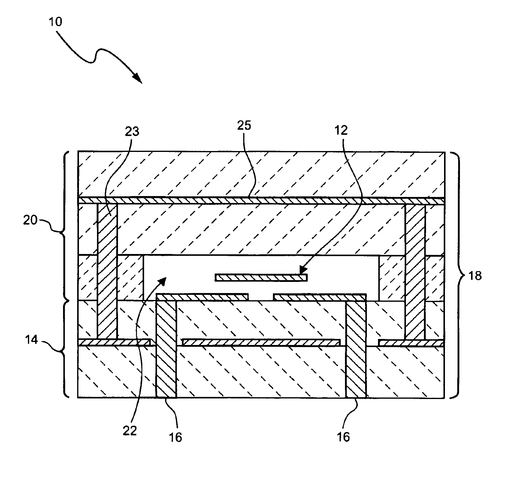
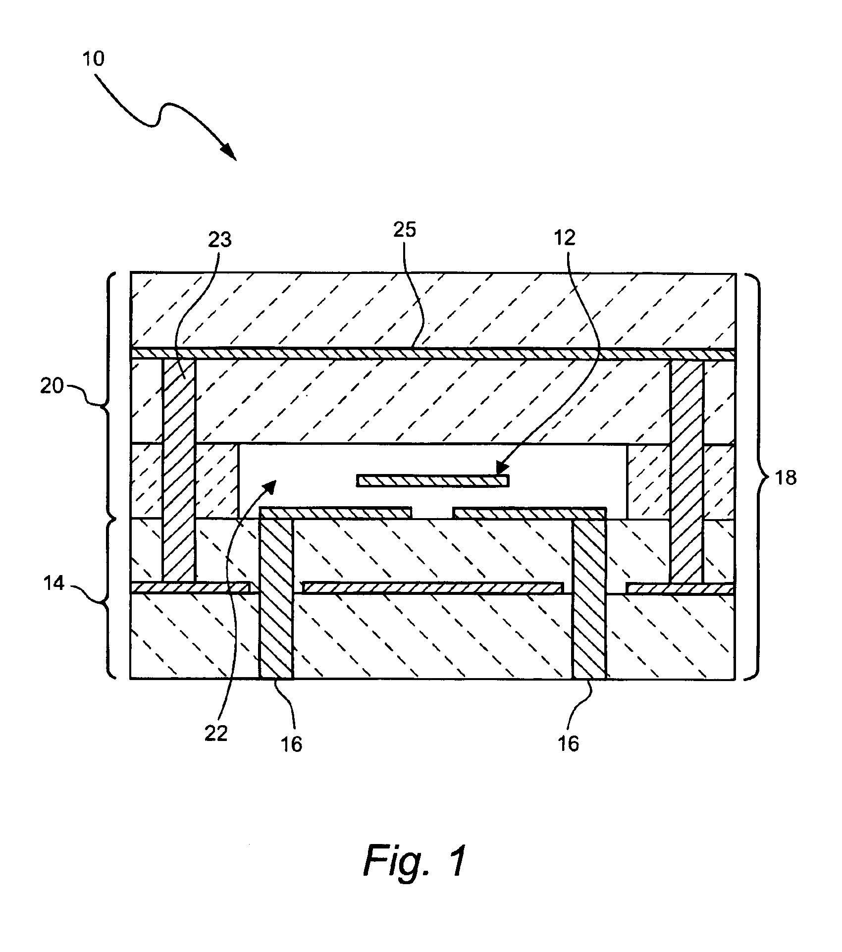
[0056]The present invention is directed to a variable capacitor, either in discrete or integrated form, which is used in electronic circuits. A sectional view of the discrete variable capacitor device 10 of the present invention is shown in FIG. 1. Variable capacitor 10 merges an electrostatically actuated micromechanical device 12 on a multi-layered substrate 14 having continuous electrical connections 16 through the layers 18 forming substrate 14. A second, upper substrate 20, made from the same material as substrate 14, is used to enclose device 12 by selectively removing a portion of upper substrate 20 to form a cavity 22 therein. Substrates 14 and 20 are then bonded together to enclose and protect the variable capacitor device 12. The bonding of the two substrates 14 and 20 can be performed, such that the enclosed cavity 22 is under partial vacuum or contains an inert ambient which may have importance to the operation and reliability of the micromechanical device 12.

[0057]The m...


PUM

PropertyMeasurementUnit
frequenciesaaaaaaaaaa
dielectric constantaaaaaaaaaa
applied actuation voltageaaaaaaaaaa

Abstract

A variable capacitor device using MEMS or micromachining techniques wherein thin-films of materials are deposited, patterned and etched to form movable micromechanical elements on the surface of a substrate composed of either semiconductor, glass, metal, or ceramic material. In one embodiment of the present invention to achieve higher frequency performance as well as other benefits, the substrate is comprised of Low-Temperature Co-Fired Ceramics (LTCC). The variable capacitor is an electrostatically actuated micromechanical device and if fabricated on a LTCC multi-layered substrate material has continuous electrical connections through the layers. The same LTCC substrate material can also be used to enclose the device by selectively removing a portion of the upper substrate so as to form a cavity. The two substrates are then bonded together to enclose and protect the variable capacitor. An integrated circuit can be incorporation onto the multi-level substrate structure to enable a electronic closed-loop controlled variable capacitor module. The integrated circuit is flip-chip bonded at the bottom of the substrate structure with appropriate electrical connections between the integrated circuit and the MEMS variable capacitor device. A variation of the present invention utilizes a zipper actuation method wherein the tuning ratio of the variable capacitor is increased to very high levels. Yet another variation of the present invention utilizes a differential gap between the top and bottom electrodes such that the actuation electrodes do not physically contact one another. Yet another implementation of the present invention uses an extra set of electrodes or mechanical mechanism so as to lock the value of the capacitor indefinitely. Yet another implementation uses shaped actuation electrodes so as to linearize the relationship between the applied actuation voltage and the resultant capacitance of the device.

Description

CROSS REFERENCE TO RELATED APPLICATION[0001]This application is based upon provisional application Ser. No. 60 / 427,584, filed Nov. 20, 2002, the disclosure of which is hereby incorporated by reference herein.FIELD OF INVENTION[0002]The present invention relates generally to variable capacitors using MEMS or micromachining technology, and in particular, to a variable capacitor device wherein the capacitive tuning ratio and quality factor is increased to very high levels, as well as a variable capacitor device where the desired capacitance value is electronically selected and held or “locked-in” using a suitable mechanical locking or bonding mechanism, or by an active closed-loop feedback control system.BACKGROUND OF THE INVENTION[0003]MEMS technology is being actively developed by many organizations for implementing components and systems for application in Radio Frequency (RF) systems. The reasons for this interest relate to the distinct advantages the MEMS technology provides over ...

Claims


Application Information

Patent Timeline
Patent Type & Authority Patents(United States)
IPC IPC(8): H01G7/06H01G7/00H01G5/00H01G5/014H01G5/18H01L23/66
CPCH01G5/014H01G5/18H01L23/66H01L2224/16H01L2924/01322H01L2924/01079H01L2924/09701H01L2924/3025H01L2924/01019H01L2924/01078
Inventor HUFF, MICHAEL A.
Owner FOR NAT RES INITIATIVES
Why Eureka
Try Eureka