Jaw structure for electrosurgical instrument

Inactive Publication Date: 2005-06-14
ETHICON ENDO SURGERY INC
View PDF157 Cites 1894 Cited by
  • Summary
  • Abstract
  • Description
  • Claims
  • Application Information

AI Technical Summary

Benefits of technology

[0010]In one exemplary embodiment, a jaw of the instrument defines a tissue engagement plane that engages the tissue targeted for welding. The engagement plane carries first and second surface portions that comprise, respectively an electrical conductor and a variable resistive body or positive temperature coefficient (PTC) material having a resistance that increases at higher temperatures. A variable resistive body of a dope polymer or ceramic can be engineered to exhibit a positively sloped curve of temperature-resistance over a temperature range of about 37° C. to 100° C. The region at the higher end of such a temperature range brackets a targeted “thermal treatment range” at which tissue can be effectively welded. The selected resistance of the variable resistive body at the upper end of the temperature range will substantially terminate current flow therethrough.
[0011]In operation, it can be understood that the engagement plane will apply active Rf energy (ohmic heating within) to the engaged tissue until the point in time that the variable resistive body is heated to exceed the maximum of the thermal treatment range. Thereafter, Rf current flow from the engagement surface will be lessened—depending on the relative surface areas of the first and second surface portions. This instant and automatic reduction of Rf energy application can be relied on to prevent any substantial dehydration of tissue proximate to the engagement plane. By thus maintaining an optimal level of moisture around the engagement plane, the working end can more effectively apply energy to the tissue—and provide a weld thicker tissues with limited collateral thermal effects.
[0012]The jaw assembly corresponding to the invention further provides a suitable cross-section and mass for providing a substantial heat capacity. Thus, when the variable resistive body is elevated in temperature to the selected thermal treatment range, the retained heat of the variable resistive matrix volume can effectively conduct thermal energy to the engaged tissue volume. Thus, in operation, the working end can automatically modulate the application of energy to tissue between active Rf heating and passive conductive heating of the targeted tissue to maintain the targeted temperature level.
[0013]The jaw assembly corresponding to the invention is moved between an open position and closed position about an engagement plane by the positive engagement of the proximally-facing cams and distally-facing cams carried by a reciprocating member. Thus, the jaw assembly can be used effectively to dissect tissue by inserting the tip of the jaw assembly into a tissue plane and then opening the jaws with substantial from to thus separate and dissect the tissue. This is not possible with many jaw assemblies of surgical instrumemts that use springs to move the jaws toward an open position.

Problems solved by technology

While such bi-polar jaws can adequately seal or weld tissue volumes that have a small cross-section, such bi-polar instruments often are ineffective in sealing or welding many types of tissues, such as anatomic structures having walls with irregular or thick fibrous content, bundles of disparate anatomic structures, substantially thick anatomic structures, or tissues with thick fascia layers such as large diameter blood vessels.
Prior art Rf jaws that engage opposing sides of a tissue volume typically cannot cause uniform thermal effects in the tissue, whether the captured tissue is thin or substantially thick.
Localized tissue desiccation and charring can occur almost instantly as tissue impedance rises, which then can result in a non-uniform seal in the tissue.
The typical prior art Rf jaws can cause further undesirable effects by propagating Rf density laterally from the engaged tissue to cause unwanted collateral thermal damage.

Method used


Image

  • Jaw structure for electrosurgical instrument
  • Jaw structure for electrosurgical instrument
  • Jaw structure for electrosurgical instrument

Examples


Embodiment Construction

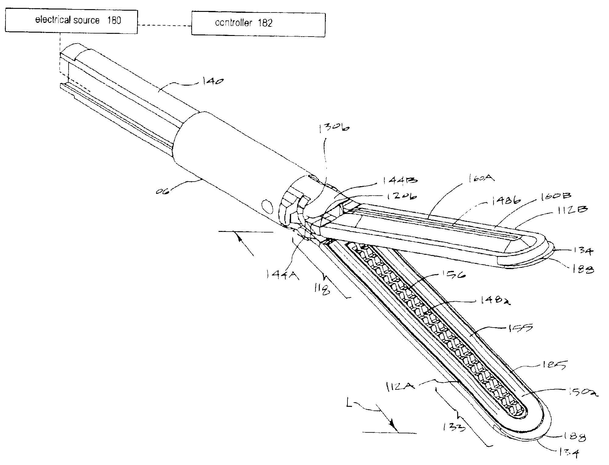
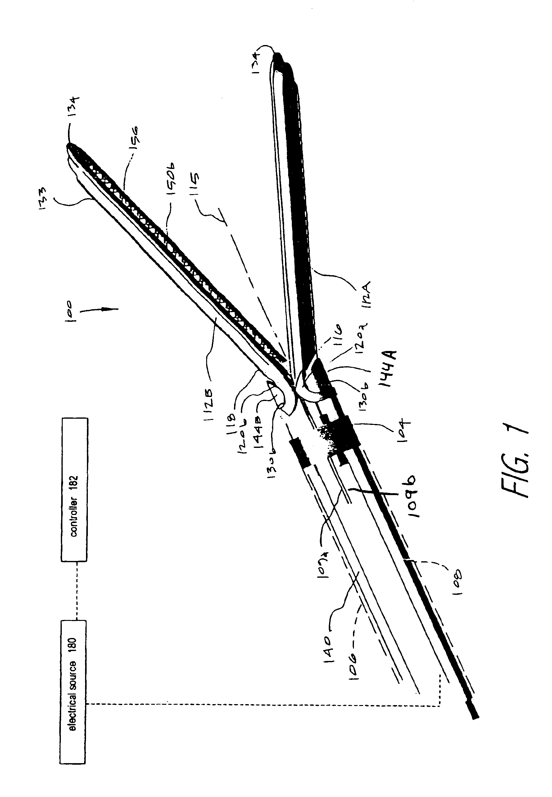
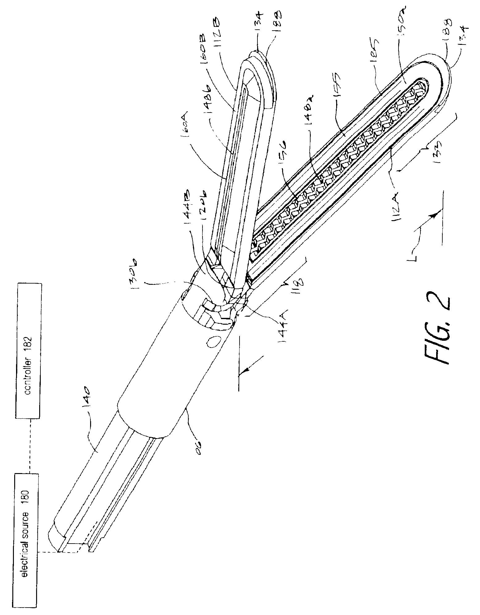
[0037]1. Type “A” jaw assembly. An exemplary Type “A” jaw assembly 100 of a surgical grasping instrument is illustrated in FIGS. 1 and 2 which is adapted for transecting captured tissue and contemporaneous welding of the captured tissue with Rf energy delivery. The jaw assembly 100 is carried at the distal end 104 of an introducer sleeve member 106 that can be rigid, articulatable or deflectable in any suitable diameter. For example, the introducer sleeve portion 106 can have a diameter ranging from about 2 mm., to 20 mm. to cooperate with cannulae in endoscopic surgeries or for use in open surgical procedures. The introducer portion 106 extends from a proximal handle (not shown). The handle can be any type of pistol-grip or other type of handle known in the art that carries actuator levers, triggers or sliders for actuating the jaws as will be disclosed below, and need not be described in further detail. The introducer sleeve portion 106 has a bore 108 extending therethrough for ca...


PUM

PropertyMeasurementUnit
Electrical conductivityaaaaaaaaaa

Abstract

An electrosurgical medical device for creating thermal welds in engaged tissue that provides general grasping and dissecting functionality. In an exemplary embodiment, at least one jaw of the instrument defines a tissue engagement plane carrying electrosurgical energy delivery means. The jaw assembly, in one mode of operation, can be used for general grasping and dissecting purposes wherein the jaws close in a non-parallel manner so that the distalmost jaw tip only engage tissue with little movement of the actuator lever in the handle of the instrument. In another mode of operation, the jaw assembly closes close in a parallel manner under very high compression to enable tissue welding.

Description

CROSS-REFERENCE TO RELATED APPLICATIONS[0001]This application claims benefit from Provisional U.S. Patent Application Ser. No. 60 / 384,429 filed May 31, 2002 having the same title, which application is incorporated herein by this reference. This application is a Continuation-In-Part of co-pending U.S. patent application Ser. No. 10 / 032,867 filed Oct. 22, 2001 titled Electrosurgical Jaw Structure for Controlled Energy Delivery, and U.S. patent application Ser. No. 10 / 079,728 filed Feb. 19, 2002 titles Electrosurgical Systems and Techniques for Sealing Tissue, both of which are incorporated herein by this reference.BACKGROUND OF THE INVENTION[0002]1. Field of the Invention[0003]This invention relates to medical devices and techniques and more particularly relates to an electrosurgical jaw structure. The jaw assembly, in one mode of operation, can be used for general grasping and dissecting purposes wherein the jaws close in a non-parallel manner so that the distalmost jaw tips only eng...

Claims


Application Information

Patent Timeline
IPC IPC(8): A61B18/14
CPCA61B18/1442A61B2018/00077A61B2018/0063A61B2018/00148A61B2018/00083
Inventor TRUCKAI, CSABABAKER, JAMES A.SHADDUCK, JOHN H.
Owner ETHICON ENDO SURGERY INC
Why Eureka
Try Eureka