
Tri-band wide wave beam circular polarization microstrip antenna

A microstrip antenna, circularly polarized technology, used in antennas, antenna coupling, devices that make antennas work in different bands at the same time, etc. In the case of antennas with three working frequency points or more, it can achieve the effect of eliminating the need for repeated debugging, reducing the deviation of working frequency points and avoiding deviation.

Active Publication Date: 2012-07-11
SUZHOU TIANYE MECHANICAL IND
View PDF4 Cites 14 Cited by
  • Summary
  • Abstract
  • Description
  • Claims
  • Application Information

AI Technical Summary

Problems solved by technology

In addition, there are many different operating frequency points in these systems. In order to ensure that each operating frequency point has a good performance, usually the existing antenna can only work on a single frequency point or two operating frequency points. There are fewer antennas that work at three or more operating frequencies, especially high-performance, compact multi-frequency circularly polarized microstrip antennas

Method used


Image

  • Tri-band wide wave beam circular polarization microstrip antenna
  • Tri-band wide wave beam circular polarization microstrip antenna
  • Tri-band wide wave beam circular polarization microstrip antenna

Examples


Embodiment Construction

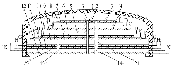
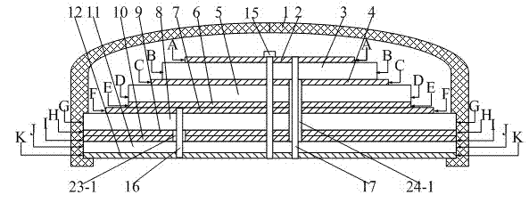
[0032] A three-band wide-beam circularly polarized microstrip antenna, comprising: a radome 1, in which a feeding network layer 12, a first dielectric layer 11, a first metal Layer 10, second metal layer 9, second dielectric layer 8, third metal layer 7, fourth metal layer 6, third dielectric layer 5, fifth metal layer 4, fourth dielectric layer 3 and sixth metal layer 2 ;

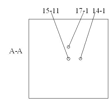
[0033] In the feed network layer 12, the first dielectric layer 11, the first metal layer 10, the second metal layer 9, the second dielectric layer 8, the third metal layer 7, the fourth metal layer 6, the third dielectric layer 5, the The central positions of the fifth metal layer 4, the fourth dielectric layer 3 and the sixth metal layer 2 are respectively provided with a first central small hole 15-1, a second central small hole 15-2, a third central small hole 15-3, and a third central small hole 15-3. 4 center holes 15-4, 5th center holes 15-5, 6th center holes 15-6, 7th center holes 15-7, 8th center...


PUM


Abstract

The invention realizes a tri-band wide wave beam circular polarization microstrip antenna, which comprises an antenna cover, wherein a feed network layer, a first medium layer, a first metal layer, a second metal layer, a second medium layer, a third metal layer, a fourth metal layer, a third medium layer, a fifth metal layer, a fourth medium layer and a sixth metal layer are sequentially stackedin the antenna cover from bottom to top and penetrated and fixed by short-circuit screws; the third metal layer is connected with the fourth metal layer; a first metallization through hole and a second metallization through hole are formed in the second medium layer and connected to the third metal layer; a Wilkinson 90-degree phase shift power divider and a four-branch 90-degree phase shift power divider are arranged on the feed network layer; a first feed needle and a second feed needle are arranged between the third metal layer and the feed network layer; and a third feed needle and a fourth feed needle are arranged between the sixth metal layer and the feed network layer.

Description

technical field [0001] The invention relates to a tri-frequency antenna suitable for satellite navigation and communication, which has excellent performances such as wide beam, high gain, small standing wave and compact structure. It is mainly used in satellite navigation and positioning receiving equipment and satellite communication receiving equipment, such as GPS receivers, GLONASS receivers, CAMPASS receivers and other navigation receiving equipment, or maritime communication satellite receiving equipment, etc. [0002] Background technique [0003] At present, satellite navigation and positioning and satellite communication have been widely used and promoted internationally, such as the GPS system in the United States, the GLONASS system in Russia, and the maritime satellite communication system, etc. In addition, the CAMPASS system in China and the GALILEO system in Europe are under construction , and the ground receivers in these systems all need antennas, and the a...

Claims


Application Information

Patent Timeline
IPC IPC(8): H01Q1/38H01Q5/00H01Q3/30H01Q13/08H01Q1/52
Inventor 曹振新夏继钢汤湘伟
Owner SUZHOU TIANYE MECHANICAL IND
Learn More