
Method and system for storm water system heat exchange

a technology of storm water and heat exchange, which is applied in the direction of indirect heat exchangers, heating types, lighting and heating apparatus, etc., can solve the problems of limited capacity, runoff may be much greater than the heat transfer coefficient between the coolant and the heat exchanger

Inactive Publication Date: 2005-06-14
MCLAUGHLIN MELVIN D
View PDF26 Cites 5 Cited by
  • Summary
  • Abstract
  • Description
  • Claims
  • Application Information

AI Technical Summary

Benefits of technology

[0019]It is a further advantage of the present invention to provide a method and system for utilizing the energy of water stored in a storm water chamber system for operation with conventional HVAC systems of buildings or other facilities located near the storm water chamber system to heat and cool these facilities.
[0020]It is a further advantage of the present invention to provide for a heat exchange system locatable within prefabricated storm water chamber chambers. It is a further advantage of the present invention to provide for an interlockable heat exchange system that is interlockable with units of a storm water chamber system.
[0021]It is a further advantage of the present invention to provide for a method and system for retaining a minimum volume of water within a storm water chamber system having a heat exchange element, such that the heat exchange element remains immersed within retained runoff in the system.
[0022]It is a further advantage of the present invention to provide for a method and system for feeding back information from the storm water chamber system to the heat exchange portion of an HVAC system of a building or other facility to increase the efficiency of the system.
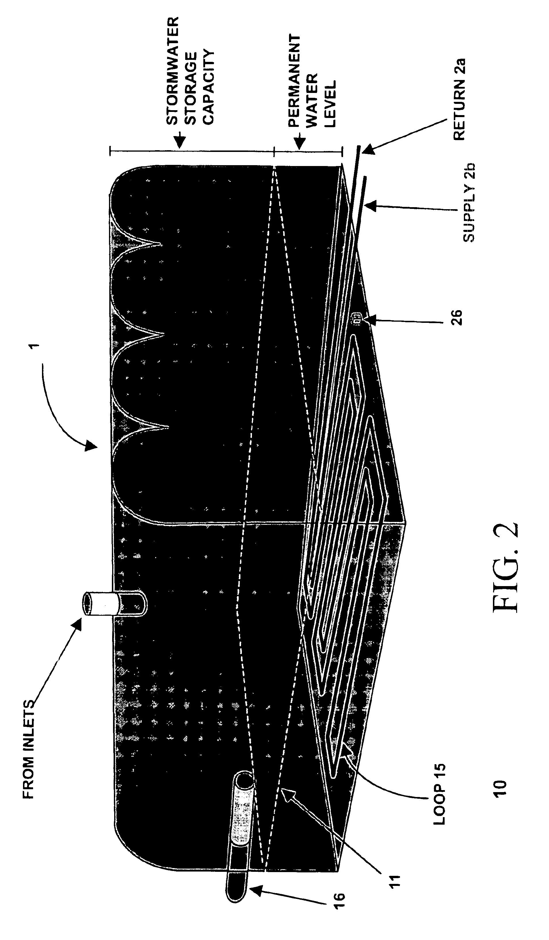
[0024]An embodiment of the present invention includes a closed loop heat exchanger system having connections by, for example, pipes containing a fluid or gas heat exchanger medium, and other components. The components of this embodiment include a pair of heat exchanger portions connected by a loop, and a pump that serves as a circulator for the heat exchange medium. In an embodiment of the present invention, the circulator moves the medium between an above ground heat exchanger, such as a radiator, for example, located in a building, and a below ground heat exchanger that includes coils located within a storm water chamber system. An embodiment of the present invention further includes a sensing device, such as a thermocouple, and feedback loop for HVAC control, to improve efficiency at ambient temperatures near the subsurface temperature.

Problems solved by technology

A problem with this approach is that the heat transfer coefficient between the coolant contained in the closed loop of the heat exchanger and the solid of the soil in which the loop is located is substantially less than the heat transfer coefficient for liquid-to-liquid or liquid to gas heat transfer.
As a result, heat transfer using soil results in inefficiency compared to heat transfer using a liquid or gas.
First flush attenuation systems are similar to retention systems; however, they have limited capacity.
After construction on such a site, however, runoff may be much greater than it was when the site was a meadow.

Method used


Image

  • Method and system for storm water system heat exchange
  • Method and system for storm water system heat exchange
  • Method and system for storm water system heat exchange

Examples


Embodiment Construction

[0032]FIGS. 1 and 2 illustrate an embodiment of the present invention that includes a closed loop heat exchanger system 1, 2a, 2b, 15 having connections by, for example pipes containing a fluid or gas heat exchanger medium, and other components. The components of this embodiment include a pair of heat exchangers portions 3, 15 connected by a loop 2a, 2b, and a pump 3 that serves as a circulator for the heat exchange medium. In an embodiment of the present invention, the circulator 3 moves the medium between an above ground heat exchanger 3, such as a radiator, for example, located in a building 4, and a below ground heat exchanger 15 that includes coils located within a storm water chamber system 1. The storm water chamber system 1 maintains a continuous level of contained runoff 11. An embodiment of the present invention further includes a storm water chamber system temperature sensing device 26, a structure internal temperature sensing device 6, which may include, for example, a t...


PUM


Abstract

A system and method for structure heating, ventilation, and air conditioning (HVAC) that uses a heat exchanger to transfer heat between the structure and a subsurface storm water discharge chamber system is disclosed. Coils for heat management exchange are located in permanently collected runoff within a storm water management system beneath the frost line; the use of coils located within the retained runoff allows for improved heat exchange over coils placed within soil. Also described are a sensing device and feedback loop for HVAC control, to improve efficiency at ambient temperatures near the subsurface temperature.

Description

CROSS-REFERENCE TO RELATED APPLICATIONS[0001]This application is a Divisional application of U.S. patent application Ser. No. 09 / 352,761, filed on Jul. 14, 1999, now U.S. Patent No. 6,412,550B1, and claims priority to provisional application, Ser. No. 60 / 108,890, filed Nov. 17, 1998, both incorporated herein by reference.FIELD OF THE INVENTION[0002]The present invention relates to use of a storm water system for heat exchange and more particularly to a method and system for using an underground storm water system for heat exchange for building heating, ventilation, and air conditioning (HVAC).BACKGROUND[0003]Many buildings and other structures for which heating or cooling is needed provide temperature control using a closed loop system having a heat exchanger. A heat exchanger requires for operation a source for adding or removing heat from the structure. A common source for adding or removing heat that is known in the art involves capture of geothermal energy, which is the energy f...

Claims


Application Information

Patent Timeline
IPC IPC(8): F24D11/00F25B29/00
CPCF24J3/086Y02E10/16F24T10/30Y02E10/10
Inventor MCLAUGHLIN, MELVIN D.
Owner MCLAUGHLIN MELVIN D
Learn More