
Thin Film Capillary Vaporization: Device and Methods

a thin film, vaporization technology, applied in lighting and heating apparatus, heating types, separation processes, etc., can solve the problems of humidifiers with thermal injuries, air inhalation of vapor, and condensation of vapor, etc., to achieve the effect of safe, efficient and quick

Active Publication Date: 2011-09-01
VAPORE
View PDF41 Cites 16 Cited by
  • Summary
  • Abstract
  • Description
  • Claims
  • Application Information

AI Technical Summary

Benefits of technology

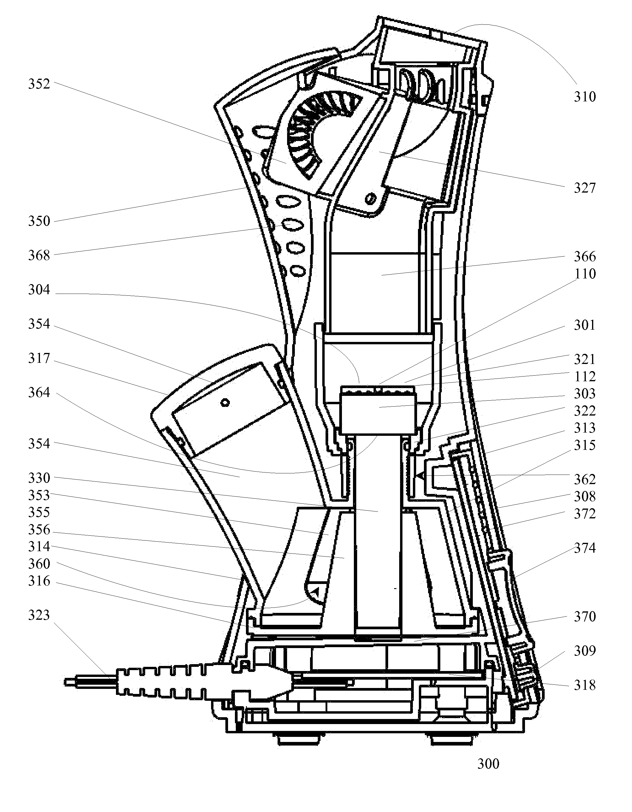
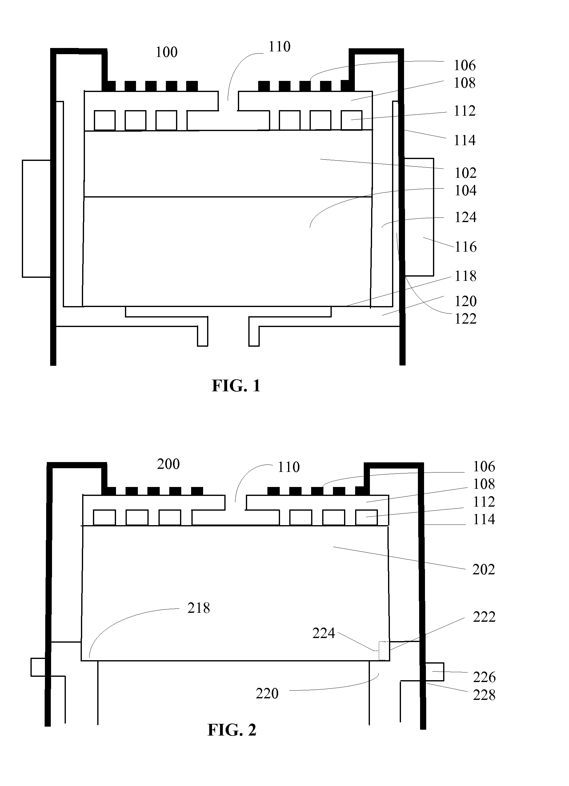
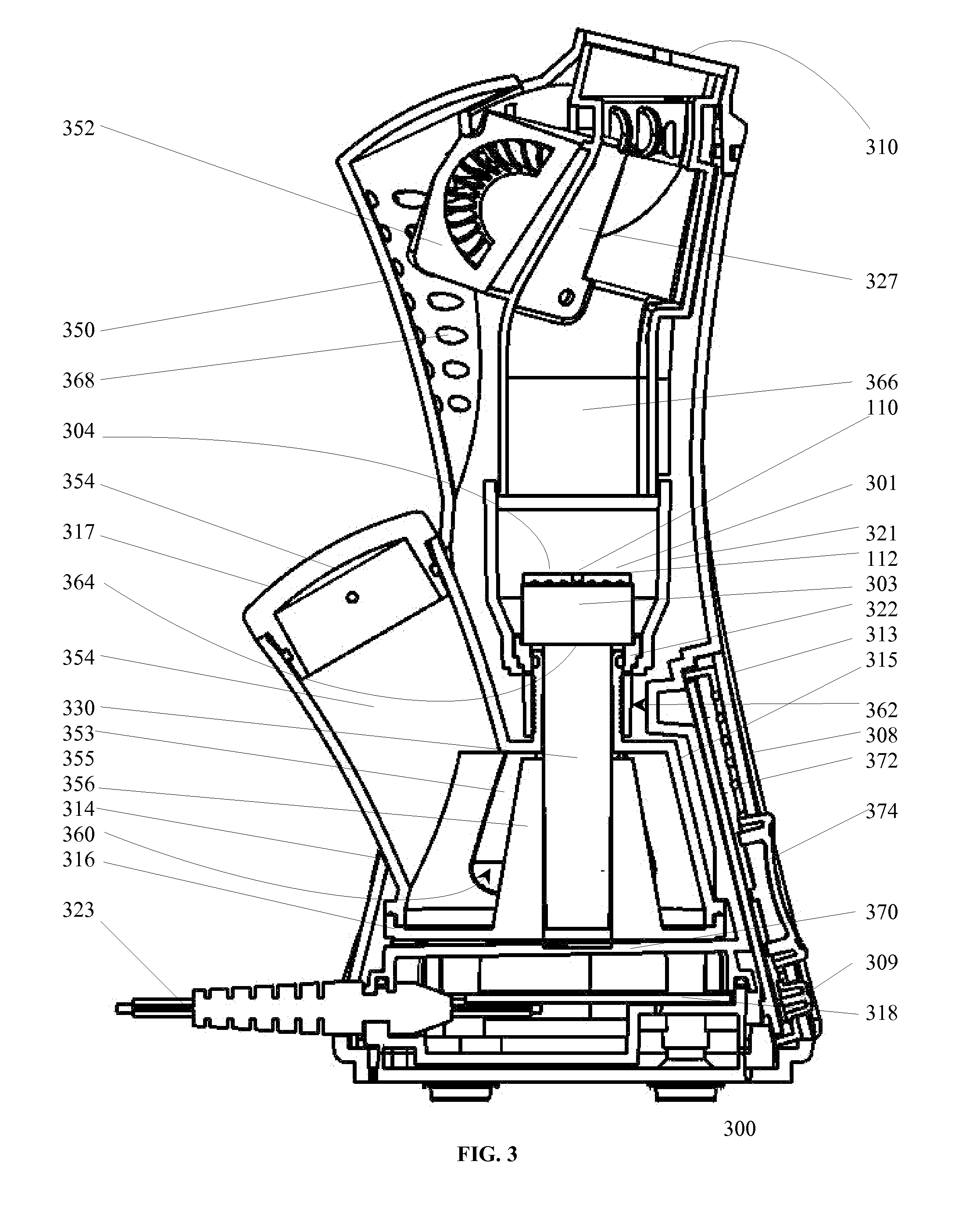
[0012]In light of the foregoing discussion, it is desirable to provide humidification that not only is free from scalding hazards and does not generally support the transmission of microbes, and bacteria and molds, in particular. Furthermore, it is desirable to provide a device that can provide humidification without requiring the heating of large quantities of water while permitting the generation of water vapor in as short a time as possible. In particular, it is desirable to deliver therapeutic or beneficial heat to an individual in a manner that is safe, efficient and can be accomplished quickly. Accordingly, the present invention provides an apparatus and method for the safe, nearly instantaneous generation of pressurized, germ-free water vapor from non-pressurized liquid feed.
[0013]Essentially, the inventive technique and device described herein involve the flash boiling of small volumes of aqueous liquid to yield heated vapor in a safe and energy-efficient manner using a lightweight, compact and portable personal vaporization device. An important aspect of the inventive vaporizers described herein is the minimal volume of aqueous feed that is vaporized. Conceptually, the amount of liquid that is vaporized at any time may be regarded as a thin film. As only very small amounts of liquid are heated to vaporization, the inventive vaporizers avoid many of the problems associated with prior art vaporizers, which typically involve the heating of large volumes of water to the boiling point. The vaporizers of the present invention therefore virtually obviate any potential hazards associated with scalding due to small amount of water that is being heated. At the same time, very little energy is required to generate vapor due to the small volume of water that requires heat in order to be vaporized. Rather than heating large volumes of water to boiling, the present invention uses energy for the flash boiling or the flash vaporization of a very small volume of water. A third feature of vaporizers of the present invention is that the generation of vapor is nearly instantaneous. Energy is used to evaporate water only at the point of egress, permitting the nearly instantaneous delivery of heat in the form of warm mist.
[0014]The difference in scale between the present invention and humidifiers of the prior art thus offers improved safety relative to commercial warm mist humidifiers and steam vaporizers. The fact that relatively small volumes of water are heated for the near flash-generation of vapor avoids the over-humidification of the immediate environment occupied by a user and means that much lower levels of energy are required to vaporize liquids. Such techniques also avoid the increased growth of mold, dust mites, and other allergens observed in areas treated with broad-scale vaporizers. A localized, directed humidification mist can obviate many of the problems observed and associated with larger-scale vaporizers of the prior art. For instance, the inventive vaporizers described herein require less water than conventional room humidifiers and can be used in domestic, commercial, indoor, outdoor, fixed as well as portable settings.

Problems solved by technology

As the popularity of humidification sources in the form of room humidifiers rose towards the latter part of the 20th century, however, humidifier-related problems surfaced.
Moreover, thermal injuries have been associated with the use of warm mist room humidifiers when abundant volumes of hot or boiling water are inadvertently spilled on a patient during humidifier use or during the time required to heat water.
Cool mist room humidifiers, on the other hand, are prone to bacterial growth in their water reservoirs and can propagate microbes during dispersion.
In addition to the foregoing problems, most prior art humidifiers require some passage of time for their liquid reservoirs to be heated to a high enough temperature to be able to provide desired vapor.
Even those vaporizers that employ a liquid supply in lieu of a reservoir are not able to generate vapor instantaneously.
Moreover, most prior art vaporizers do not protect against hazards due to inadvertent scalding.
However, neither the generation of nearly instantaneous, directed water vapor nor the denaturing or killing of microbes, or avoidance of scalding hazards are addressed.
This patent does not teach nearly instantaneous delivery of directed or pressured heated water vapor, nor the denaturing or killing of microbes.
The heater requires a ball valve, however, to prevent the delivery of water to the heater if the filter is not in place.

Method used


Image

  • Thin Film Capillary Vaporization: Device and Methods
  • Thin Film Capillary Vaporization: Device and Methods
  • Thin Film Capillary Vaporization: Device and Methods

Examples


examples

[0091]The reserved water energy of several commercial warm mist devices was calculated and compared to the inventive device. Accordingly, a Mabis Steam Inhaler Model 40-741-000 was found to hold approximately 80 ml of water, which was introduced to the device at approximately 20° C. Boiling was affected within about 2.5 minutes of power being applied. The water therefore had a reserved water energy of 4.1855 J / g·° K×80 g×(373.15° K−293.15° K)=26.8 kJ. A Vicks® Personal Steam Inhaler Model V 1200 was found to hold approximately 75 ml of water, which was also introduced to this device at 20° C. Boiling was affectuated within 10 minutes of power being applied. At this point, the water had a reserved water energy of 4.1855 J / G·° K×75 g×(373.15° K−293.15° K)=25.1 kJ. A Walgreens Personal Cough & Cold Steam Inhaler, Model FSA88 (Item Number 809729) was found to hold approximately 60 ml of water, which was also introduced at 20° C. Boiling was affectuated within about 5 minutes of power be...

example 2

[0100]Eight commercially available humidifiers were evaluated for efficacy against both bacteria and fungus and the results were compared to the performance of a thin film device according to the present invention. The prior art room humidifier devices that were used are listed here and summarized in Table 1, along with the type of mist generated—designated either cool or warm—and any mechanisms used to control germs. The prior art room humidifier devices that were used were: 1) a Vicks® Model V745A warm mist humidifier; 2) a BROOKSTONE Germ-Free Humidifier with UV Sanitizing, a cool most humidifier that includes a UV light; 3) a Kaz HWLV790, an ultrasonic cool mist humidifier that includes a UV light; 4) a HONEYWELL HCM-350 Germ Free Humidifier, an ultrasonic cool mist humidifier that includes a UV light; 5) a PLASTON Air-O-Swiss Model 7135, a cool mist humidifier with silver ion technology to control microbes; 6) a WACHSMUTH & KROGMANN Crane® EE series ultrasonic cool mist humidif...


PUM

PropertyMeasurementUnit
heightaaaaaaaaaa
heightaaaaaaaaaa
heightaaaaaaaaaa

Abstract

The present invention relates to an apparatus and method for the generation of directed vapor from a liquid source. Vaporization takes place within a device capable of confining boiling to a geometrically small volume, and expelling it as heated vapor via capillary vaporization. The foregoing is accomplished through the use of a lightweight, compact and portable personal vaporization device that generates heated vapor by the flash boiling of small volumes of aqueous liquid in a safe and energy-efficient manner. Further, the production of vapor absent microbes in aqueous systems is accomplished through the combination of microporous componentry and flash vaporization. The apparatus and methods are directed toward personal humidification for comfort and therapeutic purposes in the case of aqueous liquids, but may also be used with other, non-aqueous liquids.

Description

[0001]The present invention is a continuation-in-part of commonly-assigned and co-pending applications for patent U.S. Ser. No. 11 / 920,320 to Rabin, et al., filed 13 Nov. 2007, and U.S. Ser. No. 12 / 095,481 to Sellers, et al., filed 16 Jun. 2009.BACKGROUND OF THE INVENTION[0002]1. Field of the Invention[0003]The present invention relates to an apparatus and method for the generation and safe delivery of disinfected, therapeutic vapor. More specifically, the present invention provides a vaporizer device and vaporization method for the flash boiling of small volumes of aqueous liquid to heated vapor in a safe and energy-efficient manner using a lightweight, compact and portable personal vaporization device.[0004]2. Discussion of the Related Art[0005]One class of devices that can be used to generated vapor from liquid at room temperature is known in the art as capillary pumps, capillary vaporization modules or capillary force vaporizers. These devices generate pressurized vapor directly...

Claims


Application Information

Patent Timeline
Patent Type & Authority Applications(United States)
IPC IPC(8): F24F3/12
CPCA61M16/1075A61M16/16A61M2205/3368A61M2205/3653B01B1/08A61M16/147F24F6/08A61M16/0833A61M16/109A61M16/142B01D5/006
Inventor BRODBECK, KELLY JAMESBRESLAU, WARREN SAULDAVIDSON, ERICK MATTHEW
Owner VAPORE
Learn More