
Engine cylinder deactivation to improve the performance of exhaust emission control systems

a technology of exhaust emission control and engine cylinders, which is applied in the direction of electrical control, machine/engine, exhaust treatment electric control, etc., can solve the problems of limited acceptance of compression-ignition engines and direct-injection spark-ignition engines, high engine-out emissions of nox and pm, and low engine-out emissions of co and hc, etc., to increase the exhaust gas temperature, increase the fuel charge, and maintain the effect of engine operation

Inactive Publication Date: 2005-06-14
DELPHI TECH IP LTD
View PDF28 Cites 90 Cited by
  • Summary
  • Abstract
  • Description
  • Claims
  • Application Information

AI Technical Summary

Benefits of technology

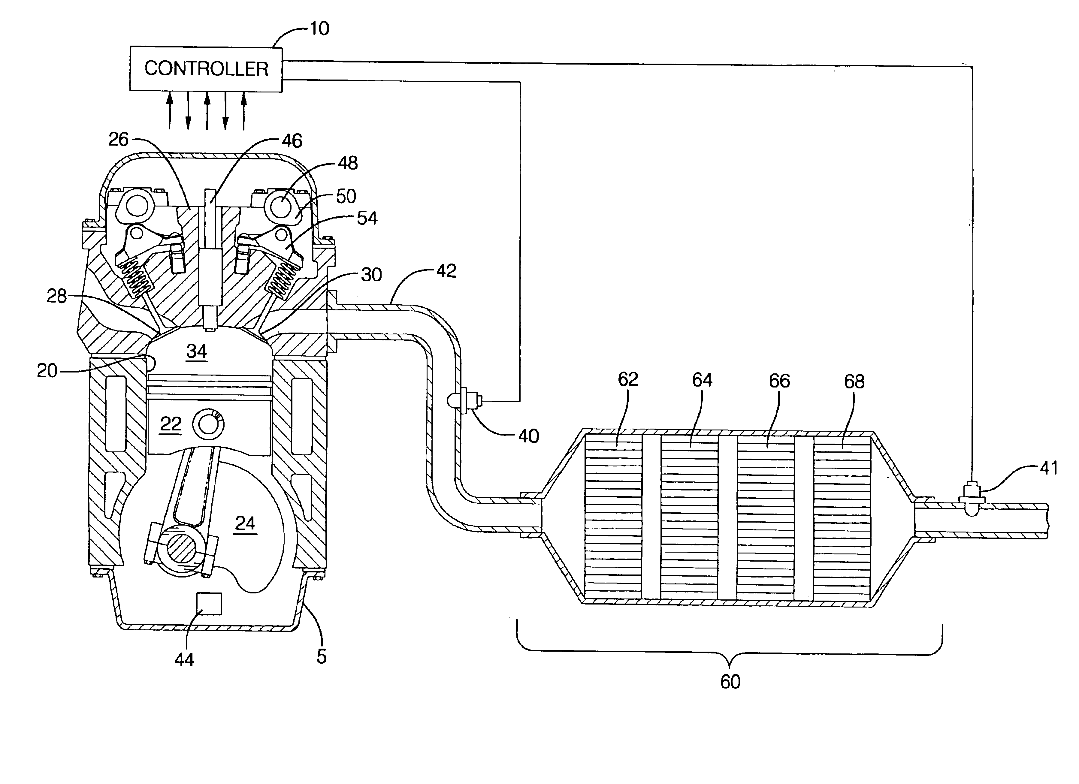
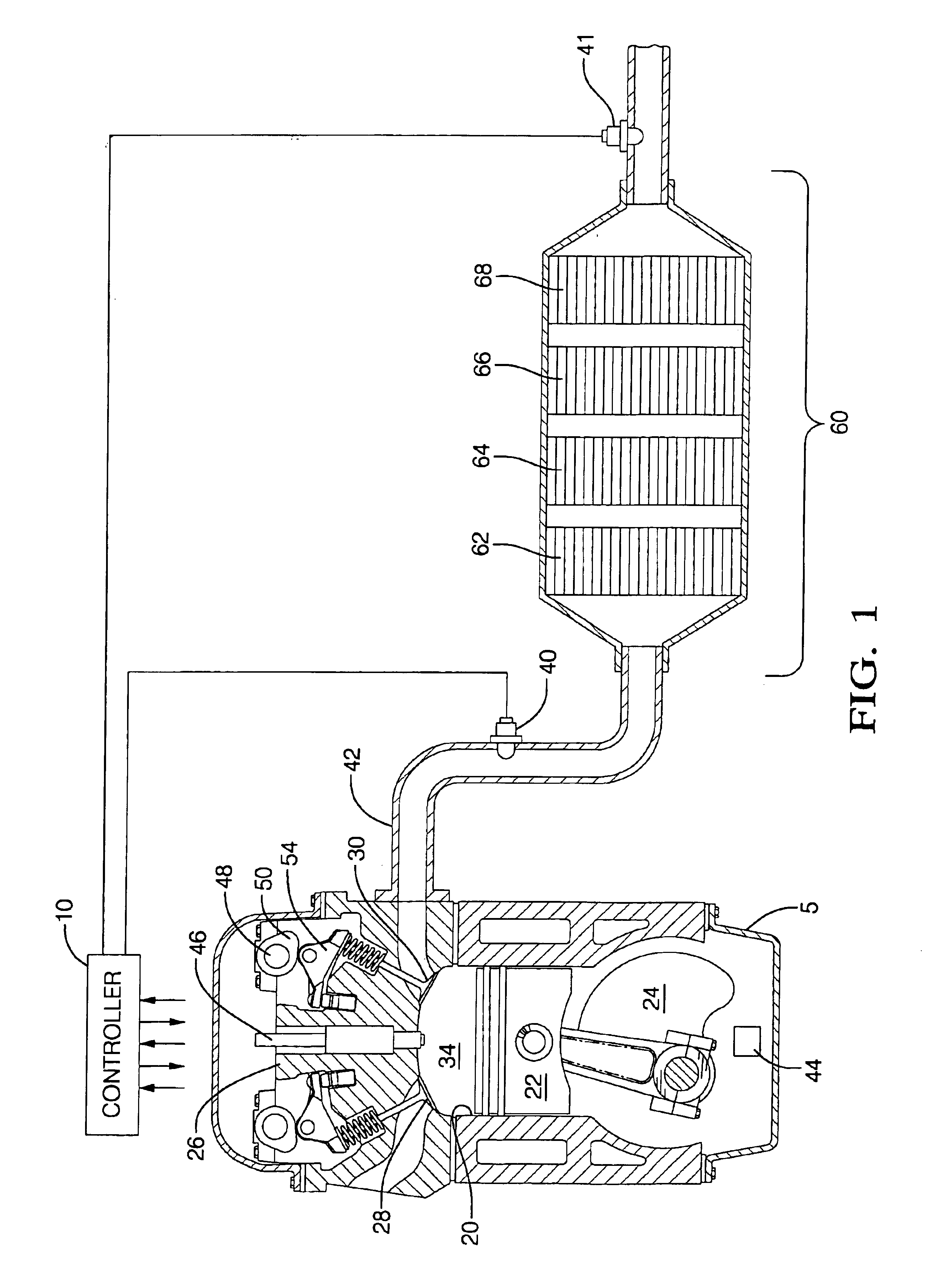
[0024]The present invention is an improvement over conventional systems to control exhaust emissions of a multicylinder engine that operates primarily at an air / fuel ratio that is lean of stoichiometry, in that it provides a controller and cylinder deactivation system to regenerate an exhaust aftertreatment device, and also to increase exhaust gas temperature. The invention uses the cylinder deactivation system to control temperature and air / fuel ratio of an exhaust gas feedstream entering an aftertreatment device. The invention also increases the fuel charge to each non-deactivated cylinder sufficient to maintain operating power of the engine. The regeneration action includes desorbing and reducing NOx from a NOx adsorber catalyst, desulfating a NOx adsorber catalyst, and purging a diesel particulate trap. The cylinder deactivation system includes disabling intake valves and exhaust valves and discontinuing fuel delivery to at least one cylinder.

Problems solved by technology

Acceptance of compression-ignition engines and direct-injection spark-ignition engines has been limited due to the inability to comply with increasingly strict emissions regulations.
When compression-ignition engines and direct-injection spark ignition engines operate with a fuel charge that is at an air / fuel ratio that is lean of stoichiometry, the result is low engine-out emissions of CO and HC.
However, lean operation also typically results in higher levels of engine-out emissions of NOx and PM.
Currently available NOx adsorber catalysts perform optimally when the temperature of the exhaust gas feedstream is in the range of 350° C. to 450° C. This exhaust gas temperature range is difficult to achieve with a compression-ignition engine or direct-injection spark ignition engine that is operated under low-speed, light load driving conditions.
These methods adversely affect fuel economy, and potentially also affect engine performance.
The performance of a NOx adsorber catalyst is negatively affected by the presence of sulfur in fuel.
As a result, adsorbed sulfates reduce the capacity of the NOx adsorber to adsorb NOx.
Overinjection may cause a release of NH3 into the atmosphere, and underinjection may result in inadequate emissions reduction.
The additional hardware to inject NH3 must be diagnosed by an onboard diagnostic system, and potentially increases warranty.
This method adversely affects fuel economy and potentially also affects engine performance.
This system may also increase HC emissions of the engine.
These approaches can increase exhaust gas temperature, but have the penalties of reducing fuel economy and increasing engine-out PM levels.
Cylinder deactivation is currently not used on compression-ignition or direct-injection spark-ignition engines primarily because there is little efficiency gain or fuel economy benefit for these engines due to the fact that the engines normally operate in an unthrottled mode with excess air.
Pumping losses reduce the total amount of energy that the engine can translate into work.
Pumping loss during air intake is due to the negative pressure in the combustion chamber that is working against the movement of the piston away from the intake and exhaust valves.
Pumping loss during exhaust is due to the positive pressure in the combustion chamber that is working against the movement of the piston toward the intake and exhaust valves.
On engines employing an air throttle device, pumping losses are great during period of low power demand.
This is caused by a large airflow restriction, and corresponding negative pressure, into the combustion chamber when the throttle device is only partially opened.

Method used


Image

  • Engine cylinder deactivation to improve the performance of exhaust emission control systems
  • Engine cylinder deactivation to improve the performance of exhaust emission control systems
  • Engine cylinder deactivation to improve the performance of exhaust emission control systems

Examples


specific embodiments

I. Light-duty Diesel Engine

[0050]When system is a light-duty diesel (i.e. compression-ignition) engine, the system comprises the engine 5 with the controller 10, the cylinder deactivation system, and the aftertreatment system 60. The aftertreatment system 60 is preferably comprised of an oxidation catalyst 62, a NOx adsorber catalyst 64, a second oxidation catalyst 66, and a diesel particulate trap 68. Each of the above-mentioned elements has been described previously. The light-duty diesel engine 5 with the controller 10, the cylinder deactivation system, and the aftertreatment system 60 is preferably operated in the NOx adsorption mode, the NOx reduction mode, the purge mode, and the desulfation mode, as described previously.

II. Heavy-duty Diesel Engine

[0051]When system is a heavy-duty diesel (i.e. compression-ignition) engine, the system comprises the engine 5 with the controller 10, the cylinder deactivation system, and the aftertreatment system 60. The aftertreatment system 60 ...


PUM


Abstract

The invention provides a controller and cylinder deactivation system to regenerate an exhaust aftertreatment device for a multicylinder engine that operates primarily at an air / fuel ratio that is lean of stoichiometry. The invention uses the cylinder deactivation system to control temperature and air / fuel ratio of an exhaust gas feedstream going into an aftertreatment device. The invention also increases the amount of fuel delivered to each non-deactivated cylinder by an amount sufficient to maintain operating power of the engine. The regeneration action includes desorbing NOx from a NOx adsorber catalyst, desulfating the NOx adsorber catalyst, and purging a diesel particulate trap.

Description

INCORPORATION BY REFERENCE[0001]Applicant incorporates by reference herein provisional Patent Application No. 60 / 334,507, which was filed in the U.S. Patent and Trademark Office on Nov. 30, 2001, and was entitled “Engine Cylinder Deactivation to Improve the Performance of Exhaust Emission Control Systems”.[0002]Applicant also incorporates by reference herein patent application Ser. No. PCT / US02 / 37813, which was filed on Nov. 25th, 2002 in the U.S. Patent and Trademark Office and is entitled “Engine Cylinder Deactivation to Improve Vehicle Interior Heating and Defrosting”.TECHNICAL FIELD[0003]This invention pertains generally to internal combustion engine control systems, and more specifically to engine valvetrain mechanisms and exhaust aftertreatment systems.BACKGROUND OF THE INVENTION[0004]Internal combustion engines, including compression ignition engines and spark ignition engines regularly undergo redesign efforts to improve efficiency and enhance fuel economy. Compression-ignit...

Claims


Application Information

Patent Timeline
IPC IPC(8): B60H1/04B60H1/00B60H1/08F01N3/023F01N3/08F02D41/02F02D41/32F02D41/36F02B1/12F02B1/00F01L13/00F01N7/00F01N9/00F01N7/02F02B75/12F02B75/00F01N13/02F02D41/00
CPCB60H1/00314F01N13/0097B60H1/08B60H1/12F01L13/0005F01N3/023F01N3/0814F01N3/0821F01N3/0842F01N3/0885F01N9/005F02B1/12F02D41/0087F02D41/024F02D41/0275B60H1/00764F01P2037/02F01P2060/08F02B2075/125F02D2250/36Y02T10/123Y02T10/26Y02T10/47Y02T10/12Y02T10/40
Inventor FOSTER, MICHAEL RALPHFOSTER, MATTHEW G.PRICE, KENNETH S.
Owner DELPHI TECH IP LTD
Learn More