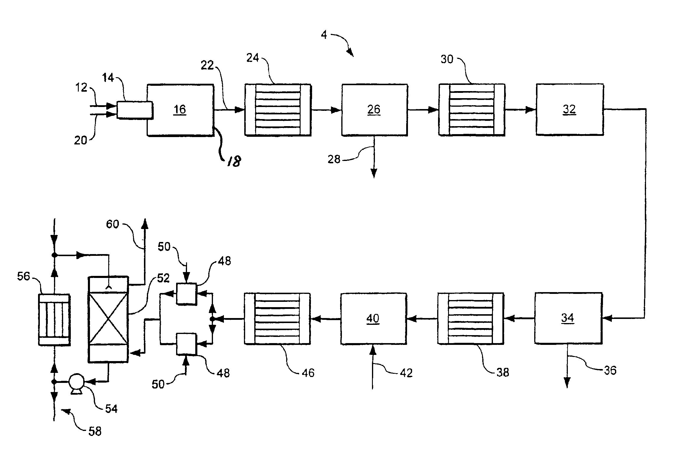
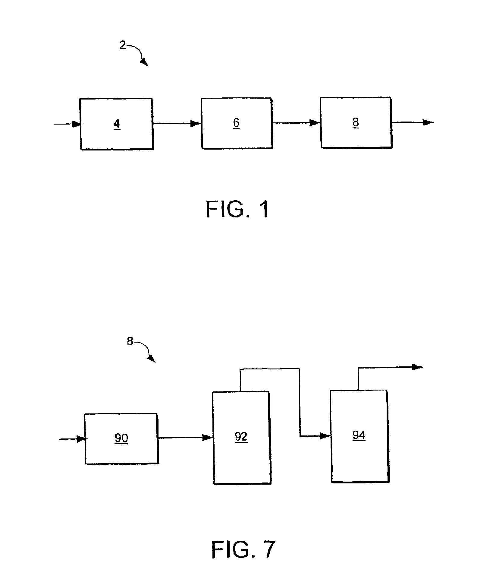
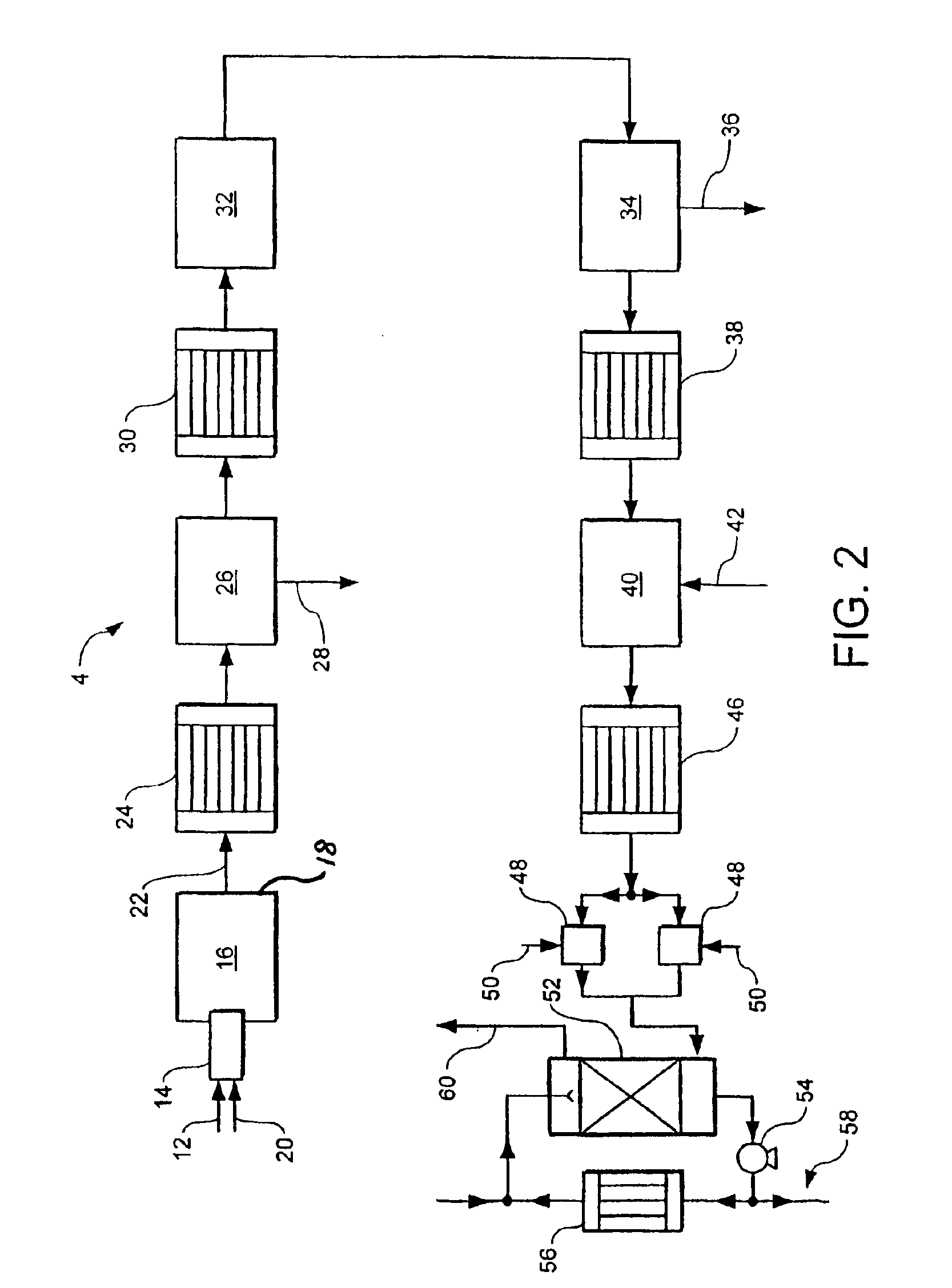
[0026]The method and apparatus according to the invention make it possible to achieve a high percentage conversion of hydrogen sulphide to sulphur upstream of the hydrogenation reactor while still obtaining a water vapour depleted gas stream sufficiently concentrated in hydrogen sulphide to enable it to be readily treatable in the Claus
plant. Accordingly, if the Claus
plant is an existing one, very high levels of uprating, typically at least 250%, and sometimes much higher can be achieved. The first catalytic Claus reactor plays a key role in making these results possible. First, it helps in gaining a high percentage conversion of hydrogen sulphide to sulphur upstream of the hydrogenation reactor. Second, substantially no hydrogen, which is typically formed in the initial furnace, is converted to water vapour in the catalytic Claus reactor. However, the sulphur dioxide concentration is decreased therein. These effects act synergistically to provide conditions in the
catalytic hydrogenation reactor which drive essentially to completion the reduction of sulphur dioxide to hydrogen sulphide therein, thereby counteracting any tendency for sulphur vapour or sulphur dioxide to breakthrough the catalytic hydrogenator while making it possible to minimise the rate at which hydrogen needs to be supplied from an
external source, or eliminating altogether the need for such an external supply. (Were such breakthrough to occur, there would be deposition of sulphur vapour intermediate the catalytic hydrogenator and the water condenser or in the condenser itself.)
[0028]Preferably, from 80% to 90% of the hydrogen sulphide is converted to sulphur vapour upstream of the
hydrogenation reaction (step (e)) in the method according to the invention. This facilitates the attainment of a high uprating of the Claus plant.
[0029]By employing an oxidant that comprises at least 80% and preferably at least 90% by volume of
oxygen, it is possible to create particularly high
flame temperatures in the first furnace. As a result of such high
flame temperatures there is considerable
thermal dissociation of hydrogen sulphide to form hydrogen and sulphur vapour. Some of the hydrogen may be oxidised in the furnace to form water vapour, but the
effluent gas from the furnace will still contain significant quantities of hydrogen. The hydrogen is further depleted by the reverse reaction with sulphur to form again hydrogen sulphide, this reverse reaction taking place as the
effluent gas stream is cooled to a temperature at which the sulphur vapour is condensed. Nevertheless, a concentration of hydrogen of at least 15% by volume (on a
dry basis, i.e. excluding water vapour) can be readily achieved at the inlet to the first catalytic Claus reactor. Such high hydrogen concentrations make it possible to operate the catalytic hydrogenator without an external supply of hydrogen.
[0030]The first furnace may have a single
combustion stage or two
combustion stages is series. If there are two combustion stages in series there is cooling between the stages. In addition there may, if desired, be an intermediate sulphur vapour condenser, and, if desired, an intermediate reheater downstream of the intermediate sulphur condenser. Thus the two stage combustion furnace may be operated with or without intermediate sulphur condensation. All these furnaces arrangements have their respective merits and drawbacks. Having two combustion stages offers the possibility of further enhancing the conversion of hydrogen sulphide to sulphur vapour but at the cost of a higher residual sulphur dioxide concentration and a lower
hydrogen concentration, both effects increasing the possibility that an external supply of hydrogen will be required in the catalytic hydrogenator. Conversion of the hydrogen sulphide to sulphur vapour can be maximised in a two combustion stage embodiment if there is intermediate sulphur condensation. If the hydrogen level falls too low an external supply of hydrogen to the catalytic hydrogenator may be employed. (In any event, it is often desirable to have an external supply of hydrogen present so as to facilitate
start up of the method and apparatus according to the invention.)
[0035]Conventionally, in Claus processes,
oxygen for reaction with hydrogen sulphide is supplied at a rate approximately equal to 0.33c. By operating with substantially less oxygen the hydrogen sulphide to sulphur dioxide ratio in the furnace is kept up thereby favouring the reduction of sulphur dioxide to sulphur vapour. Thus, in two combustion stage examples a
mole ratio of hydrogen sulphide to sulphur dioxide preferably in the range of 4:1 to 10:1, can be obtained at the inlet to the first catalytic Claus reactor, and in single combustion stage examples a substantially high
mole ratio may be achieved. Such high ratios again help to convert sulphur dioxide to sulphur in the first catalytic Claus reactor. On the other hand, the lower the rate of
oxygen supply, the lower the actual conversion of hydrogen sulphide to sulphur achieved in the first furnace and the lower the
flame temperature in the first furnace.
[0041]Operation of the first catalytic Claus
reaction step and the first furnace in accordance with the preferred aspects of the method according to the present invention make it possible to achieve a sulphur dioxide concentration (on a
dry basis) in the further sulphur depleted gas stream of less than 1% by volume. The combination of a high in situ
hydrogen concentration at the inlet to the catalytic hydrogenator with a low sulphur dioxide concentration facilitates complete reduction of residual sulphur dioxide to hydrogen sulphide in the
catalytic hydrogenation step without the need to supply hydrogen from an
external source to the catalytic hydrogenator. The external hydrogen may be supplied from a source of pure hydrogen, or in a mixture with another gas or gases, for example
carbon monoxide, particularly from a reducing
gas generator.


