
Radiation source for generating extreme ultraviolet radiation

a radiation source and radiation source technology, applied in the direction of x-ray tubes, nuclear engineering, active medium materials, etc., can solve the problems of minor radiation impingement on the second detector, and the calibration of the energy monitor unit is retained

Inactive Publication Date: 2005-04-19
USHIO DENKI KK
View PDF14 Cites 45 Cited by
  • Summary
  • Abstract
  • Description
  • Claims
  • Application Information

AI Technical Summary

Benefits of technology

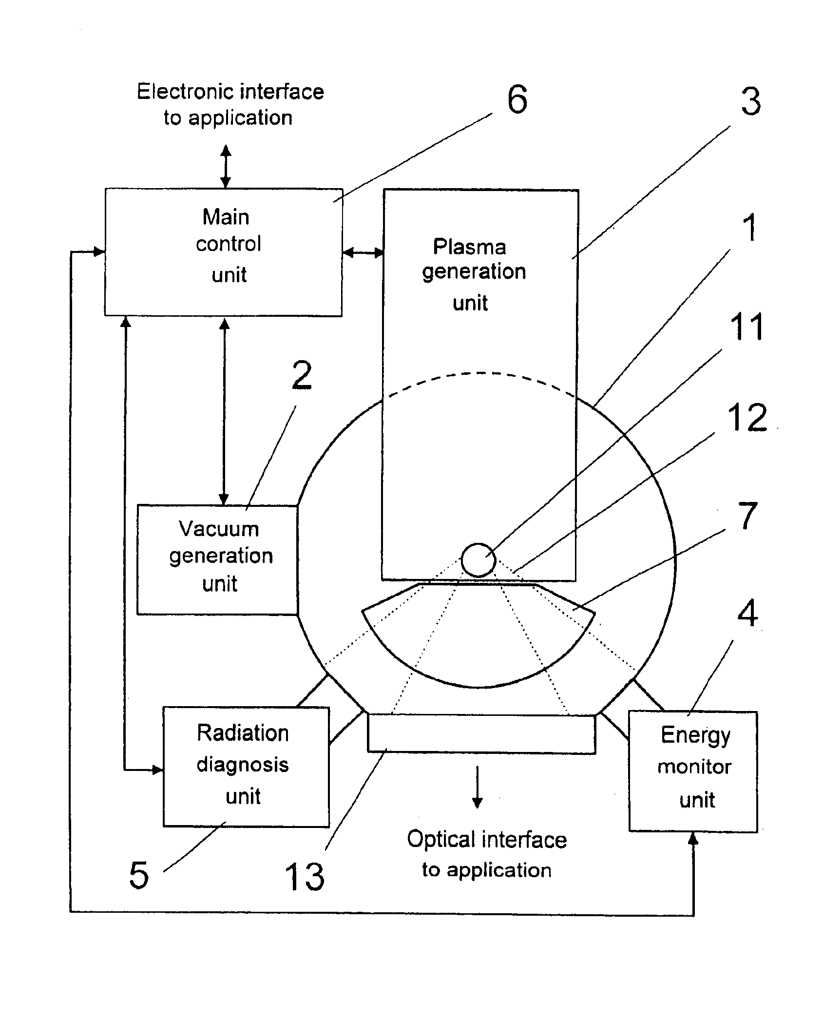
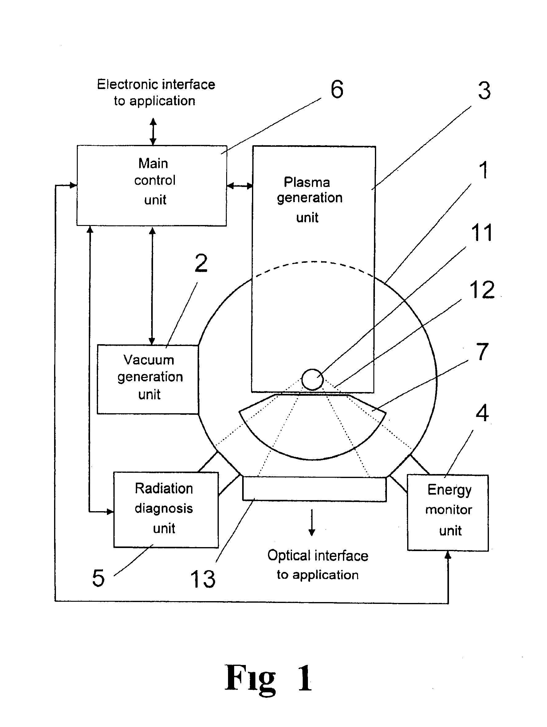
The invention is a new way to generate extreme ultraviolet (EUV) radiation for use in various applications. The invention involves a vacuum chamber where a plasma is generated and a hot plasma is generated in a small space with high density. The plasma is generated by a plasma generation unit that is directly connected to the vacuum chamber and introduces high energy input in a pulsed manner. The plasma generation unit has a detector for measuring the pulse energy of the emitted radiation. The energy monitor unit has a feedback mechanism to regulate the stability of the plasma generation. The radiation diagnosis unit analyzes the actual radiation characteristics and provides data for influencing the excitation conditions of the plasma. The main control unit controls the radiation source to achieve the desired beam characteristics. The invention allows for a flexible and reproducible radiation source for generating extreme ultraviolet (EUV) radiation.

Problems solved by technology

Since the second energy detector is used only rarely and briefly for calibration and is concealed the rest of the time, the degradation of the second detector caused by the impinging radiation is minor and the absolute calibration of the energy monitor unit is retained for a long period of time.

Method used


Image

  • Radiation source for generating extreme ultraviolet radiation
  • Radiation source for generating extreme ultraviolet radiation
  • Radiation source for generating extreme ultraviolet radiation

Examples


example 1

Radiation Source Based on Gas Discharge Plasma

[0045]There are many known constructions of EUV radiation sources based on gas discharges, in all of which a high voltage generated in a pulsed manner in a work gas under low pressure discharges by means of rotationally symmetric electrodes. As a result of the occurring high current densities, the discharge plasma implodes to form a hot plasma within a very limited space.

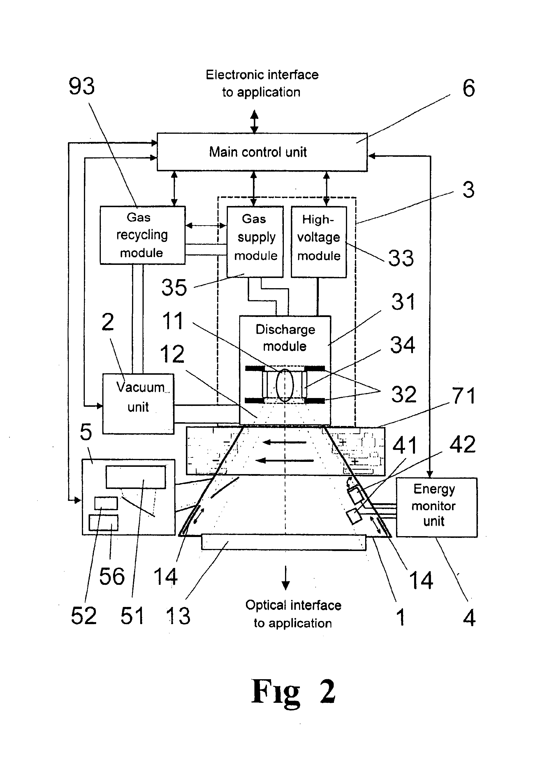
[0046]For gas discharge of the kind mentioned above, the plasma generation unit 3 according to FIG. 2 has a discharge module 31 with electrodes 32 which are suitably shaped for through-flow of gas, a high-voltage module 33 for generating the required high voltage and for gas flow through the electrodes 32, and a gas supply module 35 which provides a work gas (e.g., containing a substantial proportion of a rare gas, preferably xenon) in a vacuum chamber 1 in a composition suitable for plasma generation.

[0047]The high-voltage module 33 has a capacitor bank which can charge...

example 2

Laser-Pumped EUV Radiation Source

[0079]In this example, a laser beam producing the required energy input for plasma excitation is directed to a target flow in order to generate the EUV-emitting plasma 11. However, other high-energy radiation, e.g., an electron beam, is equally suitable for generating the plasma.

[0080]In the laser-pumped radiation source shown in FIG. 4, a laser module 36 containing a pulsed laser which emits pulses with lengths of between 50 fs and 50 ns is provided in the plasma generation unit 3. The pulse energy of laser modules 36 of this kind is typically between 1 mJ and 10 J per pulse.

[0081]The wavelength and pulse energy of the laser beam are determined by parameters of the laser module 36 and an internal control. The pulse energy can be varied by pump output, variation of attenuators, etc. The laser module 36 determines suitable parameters of the laser by means of the control and checks that the required specifications are maintained in relation to output p...


PUM

PropertyMeasurementUnit
widthsaaaaaaaaaa
thermal energyaaaaaaaaaa
wavelength rangeaaaaaaaaaa

Abstract

The invention is directed to a radiation source for generating extreme ultraviolet (EUV) radiation, particularly for photolithography exposure processes. The object of the invention is to find a novel possibility for realizing radiation sources for generating extreme ultraviolet (EUV) radiation which permits a uniform basic construction for ensuring beam characteristics that are reproducible over the long term and in which the source is conceived so as to be flexible with respect to specific applications. This object is met according to the invention in that any plasma generation unit is provided for introducing high energy input supplied in a pulsed manner in a vacuum chamber, and the radiation generated from the plasma is monitored by an energy monitor unit which measures the pulse energy of the emitted radiation and by a radiation diagnosis unit which detects the radiation characteristics to obtain result data for influencing the excitation conditions for the plasma and to influence the parameters of the plasma generation in an application-specific manner by means of the main control unit.

Description

CROSS-REFERENCE TO RELATED APPLICATIONS[0001]This application claims priority of German Application No. 102 51 435.6, filed Oct. 30, 2002, the complete disclosures of which are hereby incorporated by reference.BACKGROUND OF THE INVENTION[0002]a) Field of the Invention[0003]The invention is directed to a radiation source for generating extreme ultraviolet (EUV) radiation, particularly for photolithography exposure processes. It is preferably applied in the semiconductor industry for the fabrication of semiconductor chips with structure widths of less than 50 nm.[0004]b) Description of the Related Art[0005]Gas discharge plasmas and laser-induced plasmas are known as emitters of EUV radiation. Different applications of this radiation are currently under examination, e.g., lithography, microscopy, reflectometry and surface analyses. Intensive, dependable radiation sources are required for all of these different applications.[0006]EUV radiation sources will be required in the future prim...

Claims


Application Information

Patent Timeline
Patent Type & Authority Patents(United States)
IPC IPC(8): G21K5/04H05G2/00
CPCH05G2/003
Inventor SCHRIEVER, GUIDOGAEBEL, KAISTAMM, UWE
Owner USHIO DENKI KK
Learn More