
Method of manufacturing a glass substrate and a magnetic recording medium

a technology of glass substrate and magnetic recording medium, which is applied in the field of magnetic recording medium manufacturing, can solve the problems of insufficient record/reproduce characteristic, inability to obtain magnetic disks having excellent magnetic characteristics, and inability to meet the recent strict demand for conventional magnetic recording medium, etc., to achieve stable and excellent magnetic characteristics, suppress the variation of surface roughness, and the surface roughness of glass substra

Inactive Publication Date: 2005-04-12
HOYA CORP
View PDF16 Cites 19 Cited by
  • Summary
  • Abstract
  • Description
  • Claims
  • Application Information

AI Technical Summary

Benefits of technology

This invention is performed based upon the above-mentioned analyzed result. It is an object of this invention to provide a magnetic recording medium which has a stable and excellent magnetic characteristic and which is capable of recording and reproducing at a high density.
According to this invention, the surface roughness of the glass substrate and the variation of the surface roughness are suppressed to the predetermined range. Namely, the surface roughness (Rmax, Ra, Rq) and the relation (Rmax/Ra) between Rmax and Ra are restricted to the predetermined range. In this event, Ra is representative of a center-line m...

Problems solved by technology

However, according to inventor's research, it has been found out that the magnetic characteristic, such as the coercive force and the S / N ratio, and the record / reproduce characteristic do not sufficiently satisfy the recent strict demand in the conventional magnetic recording medium.
Namely, even when the magnetic recording media are manufactured in the condition that the surface roughness of the glass substrate and the manufacturing condition of the magnetic layer formed thereon are made uniform, the magnetic disk having an excellent magnetic characteristic can not be always obtained.
As a result, it has been concluded that the cause results in the variation of the surface roughness of the glass substrate, and the crystal growth of a thin film formed thereon, such as the magnetic layer, is disturbed due to the variation to deteriorate the magnetic characteristic and the record / reproduce characteristic.
Namely, even when the magnetic media are manufactured in the condition that the surface roughness of the glass substrate and the magnetic layer formed thereon are kept in the same manufacturing condition, the magnetic disk having stable and excellent magnetic characteristic can not be always obtained.

Method used

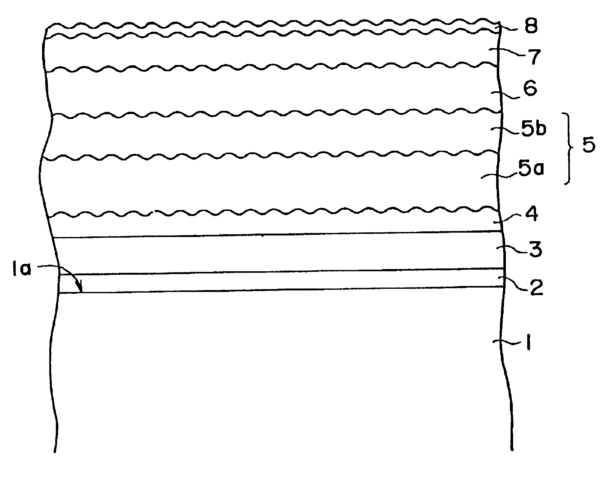
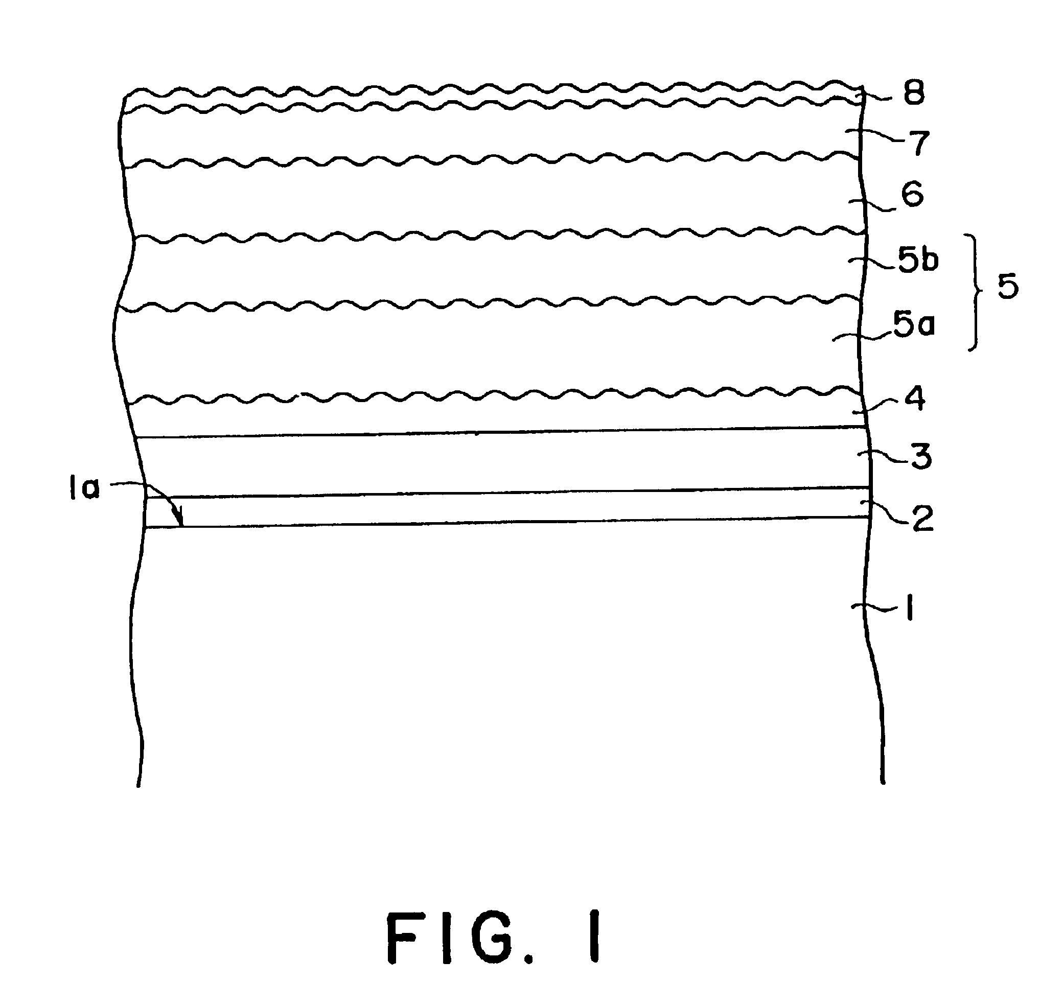
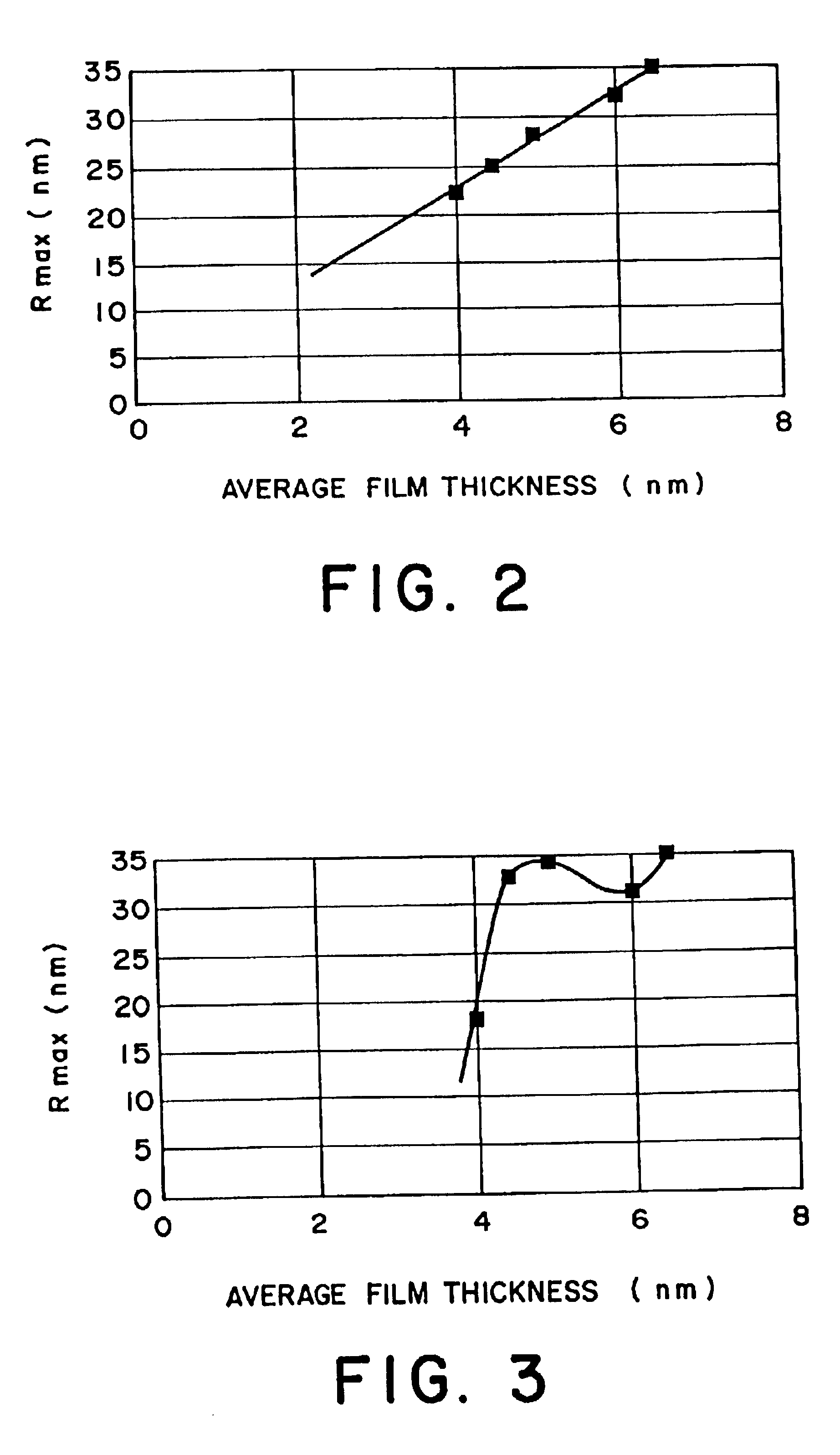

Image

  • Method of manufacturing a glass substrate and a magnetic recording medium
  • Method of manufacturing a glass substrate and a magnetic recording medium
  • Method of manufacturing a glass substrate and a magnetic recording medium

Examples


examples 2 to 4

, COMPARATIVE EXAMPLES 1 TO 4

The magnetic recording medium was manufactured in the same manner as the above-mentioned example 1 except that the polishing condition and the surface roughness of the glass substrate were changed. Thus, examples 2 to 4 and comparative examples 1 to 4 were made. The surface roughness Ra (nm), Rmax (nm) of the principal surface of the glass substrate, Rmax / Ra, the coercive force Hc (Oe), the S / N ratio (dB), Cp and the result of the CSS durability test are represented for the examples 2 to 4 and comparative examples 1 to 4 in Table 1.

TABLE 1CpCpCSSRmaxRaRmaxHc(bothS / N(LowerDura-(nm)(nm)Ra(Oe)sides)(dB)limit)bilityExample12.60.2311.31900-20002.424.2-25.85.3◯215.01.311.51850-20501.621.5-24.13.7◯310.00.810.51865-20351.822.2-24.64.5◯45.00.511.01875-20252.222.9-25.15.1◯ComparativeExample118.51.215.41810-20901.220.4-23.63.0◯214.31.410.21830-20701.321.3-23.93.5◯39.01.09.01840-20601.521.9-24.54.0X418.41.710.81800-21001.119.5-23.52.9Δ

From the above-mentioned result...

examples 5 to 11

, COMPARATIVE EXAMPLES 5 TO 9

The magnetic recording medium was manufactured in the same manner as the above-mentioned example 1 except that the polishing condition and the surface roughness of the glass substrate were changed, the average film thickness of the first underlying layer 2 was set to 1 nm and the surface roughness (Rmax) of the irregularity forming layer was set to 24 nm. Thus, examples 5 to 11 and comparative examples 5 to 9 were made. The surface roughness Ra (nm), Rmax (nm), Rq (nm) of the principal surface of the glass substrate, Rmax / Ra, the average crystal grain size (nm) of the magnetic layer, the S / N ratio (dB) and the presence or absence of the head crash are represented for the examples 5 to 11 and comparative examples 5 to 9 in Table 2.

TABLE 2CrystalGrainSurface RoughnessSize ofof SubstrateMagneticRaRmaxRqLayerS / NHead(nm)(nm)(nm)Rmax / Ra(nm)(dB)CrashExample 50.252.550.3110.21124.7◯ 60.337.770.3923.51324.4◯ 70.429.800.5023.31524.0◯ 80.4612.00.5826.11822.8◯ 90.68...

examples 16 to 20

, COMPARATIVE EXAMPLES 14 TO 16

The magnetic recording media were manufactured by adjusting the film thickness of the irregularity forming layer and the sputtering condition in the same manner as the example 5 except that the surface roughness of the irregularity forming layer was changed into 9 nm (comparative example 14), 10 nm (example 16), 20 nm (example 17), 30 nm (example 18), 40 nm (example 19), 50 nm (example 20) and 55 nm (example 15). Further, the magnetic recording medium was manufactured in the same manner as the example 5 except that the irregularity forming layer having the surface roughness (Rmax) of 10 nm was formed on the glass substrate of the above-mentioned comparative example. In this event, the surface roughness of the irregularity forming layer, the CCS durability and the characteristic of the head crash are represented in Table 5.

TABLE 5RmaxCSS DurabilityHead(nm)(100,000 times)CrashComparativeExample149X◯Example1610◯◯1720◯◯1830◯◯1940◯◯2050◯◯ComparativeExample1...


PUM

PropertyMeasurementUnit
Grain sizeaaaaaaaaaa

Abstract

In a magnetic recording medium, surface roughness of a glass substrate and the variation of the surface roughness are suppressed to the predetermined range. Namely, the surface roughness (Rmax, Ra, Rq) and the relation (Rmax / Ra) between Rmax and Ra are restricted to the predetermined range. In this event, Ra is representative of a center-line mean roughness, Rmax is defined as a maximum height representative of a difference between a highest point and a lowest point and Rq is representative of a root mean square roughness. Thereby, crystal grains of an underlying layer and a magnetic layer formed thereon are equalized. Specifically, the surface roughness is specified by Rmax≦15 nm, Ra≦1 nm and Rq≦1.5 nm. Further, the ratio between the surface roughness Rmax and the surface roughness Ra is specified by Rmax / Ra≦30.

Description

BACKGROUND OF THE INVENTIONThis invention relates to a magnetic recording medium for recording and reproducing at a high density, a glass substrate for the magnetic recording medium and a method of manufacturing the same.Recently, a magnetic disk having a high recording density has been demanded. To achieve the high recording density, it is important to reduce a flying height of a magnetic head for a surface of a magnetic recording medium. In recent years, it has been required that the flying height falls within the range between 0.1 and 0.2 μm. To satisfy such a requirement, the magnetic disk having the high recording density has been developed as disclosed in Japanese Unexamined Patent Publications Nos. H5-303735 and H8-293177.In the magnetic disk disclosed in the above-mentioned Japanese Unexamined Patent Publication No. H5-303735, an annular-shape substrate (glass substrate) has a surface roughness Ra of 1 μm or less and a flatness of 1 μm or less. Thereby, the flying height of ...

Claims


Application Information

Patent Timeline
IPC IPC(8): C03C19/00G11B5/73G11B5/84G11B5/62
CPCC03C19/00G11B5/7315G11B5/8404G11B5/7325C03C2204/08Y10T428/315Y10S428/90Y10T428/24355G11B5/73921
Inventor WATANABE, TSUYOSHITAKAHASHI, KOJITAKANO, MASAO
Owner HOYA CORP
Learn More