
Fluorinated silica microchannel surfaces

a microchannel and fluorinated silica technology, applied in the field of silicon-based microchannels, can solve the problems of insufficient prior art reduction or elimination of deformation of mobile polymer monoliths, difficult fabrication, etc., and achieve the effect of reducing the resistance to material movement, reducing the free energy of the surface, and precise and rapid protocol

Inactive Publication Date: 2005-03-15
SANDIA NAT LAB
View PDF7 Cites 8 Cited by
  • Summary
  • Abstract
  • Description
  • Claims
  • Application Information

AI Technical Summary

Benefits of technology

Accordingly, the present invention is directed to methods for reducing resistance to material movement in microchannels. The method provides a precise and rapid protocol for modification of the microchannel surface to produce a surface having a programmably lowered surface free energy, thereby reducing the friction coefficient of the interface between the microchannel and mobile elements, fabricated therein, in a controllable manner. In particular, the method provides for modifying the surfaces of silica flow channels, by attaching an uncharged and chemically inert fluorinated alkane group to the surface. The fluorinated group is chemically similar in to Teflon® and shows similar low friction properties.

Problems solved by technology

However, selection of appropriate charged moieties can present fabrication difficulties and the prior art did not address changes in surface energy of uncharged species to effect reduction in the coefficient of friction between channel walls and the mobile polymer monolith.
Moreover, there is no provision in prior art for reducing or eliminating deformation of the mobile polymer monolith.

Method used


Image

  • Fluorinated silica microchannel surfaces
  • Fluorinated silica microchannel surfaces

Examples


example 1

A microchannel was filled with a solution of 1,4-dioxane, acetic acid, water and (tridecafluoro-1,1,2,2-tetrahydrooctyl) triethoxysilane. The solution was heated to 70° C. and remained in contact with the microchannel walls for about 2 hrs. The ethoxy groups undergo hydrolysis and react with the silanol (SiOH) groups on the silica microchannel wall to attach the fluorinated alkane to the microchannel wall. The fluorinated alkane projects from the silica wall and lowers the surface energy, and thus the frictional resistance of the channel wall. That coating the internal surface of a microchannel with a low friction coefficient fluorocarbon coating is effective in reducing wall friction is illustrated in the Example below.

example 2

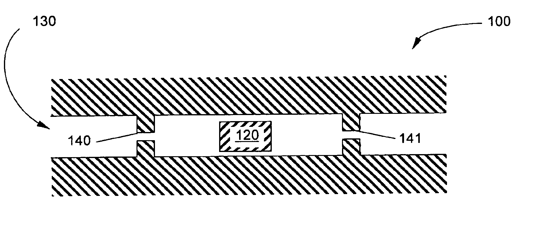
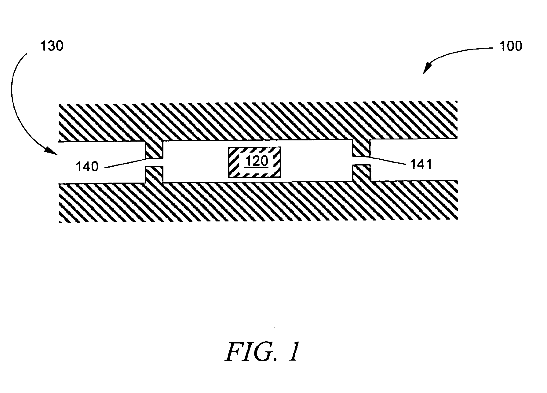
A pair of devices similar in design to that shown in FIG. 1 was prepared. These devices 100 comprised a mobile monolithic polymer element 120 disposed within a microchannel 130, provided with first and second inlets and retaining means 140 and 141. The microchannel in one of devices 100 was coated with a fluorocarbon coating by the method described in example 1 above. Monolithic polymer elements were fabricated within each of the microchannels by methods such as those described in U.S. patent application Ser. Nos. 09 / 695,816 and 10 / 141,906 and conform to the shape of the microchannel.

Hydraulic pressure, applied by pressure means such as an HPLC pump or an electrokinetic pump (such as described in U.S. Pat. Nos. 6,013,164 and 6,019,882 to Paul and Rakestraw), to either end of element 120 caused polymer elements to move one direction or the other in response to the applied pressure. It was found in every case that the pressure required to actuate the polymer element within the fluoroc...


PUM


Abstract

A method for surface modification of microchannels and capillaries. The method produces a chemically inert surface having a lowered surface free energy and improved frictional properties by attaching a fluorinated alkane group to the surface. The coating is produced by hydrolysis of a silane agent that is functionalized with either alkoxy or chloro ligands and an uncharged C3-C10 fluorinated alkane chain. It has been found that the extent of surface coverage can be controlled by controlling the contact time from a minimum of about 2 minutes to a maximum of 120 minutes for complete surface coverage.

Description

CROSS-REFERENCE TO RELATED APPLICATIONSNot applicable.FIELD OF THE INVENTIONThe present invention is directed to a method for reducing resistance to material movement in microchannels and capillaries, and especially in silica-based microchannels. The method provides for application of a chemically inert coating to the internal surfaces of these microchannels to produce a surface having a lowered surface free energy, thereby reducing frictional resistance between the microchannel wall and mobile components contained therein.BACKGROUND OF THE INVENTIONMicrovalves have been fabricated from monolithic polymer materials for use in controlling fluid flow in microfluidic systems. These microvalves are typically fabricated by photoinitiating phase-separated polymerization in specified regions of a three-dimensional microstructure that can be of glass, silicon, or plastic. The valve function is achieved by controlling the shape of the polymer monolith and by designing the monolith to move fr...

Claims


Application Information

Patent Timeline
IPC IPC(8): B05D5/08B05D3/02
CPCB05D5/083B05D3/0254B05D2254/04B05D2203/30
Inventor KIRBY, BRIAN J.SHEPODD, TIMOTHY JON
Owner SANDIA NAT LAB
Learn More