
Method and apparatus for kinematic registration of a reticle

Inactive Publication Date: 2005-03-08
ASML HLDG NV
View PDF28 Cites 28 Cited by
  • Summary
  • Abstract
  • Description
  • Claims
  • Application Information

AI Technical Summary

Benefits of technology

The invention provides an improved reticle frame structure with a variety of embodiments. In an embodiment of the invention, a device registers the reticle substrate when that reticle is loaded into it, holds and secures the reticle with its mask side down and minimal contact to it, interfaces with robotic end effectors, grippers, or the like, in place of the reticle, to enable its manipulation without extra contact, releases the reticle to the lithography system's positioning device without any actuation, and interfaces with a SMIF pod, in place of the reticle, to assist in centering and securing the reticle.
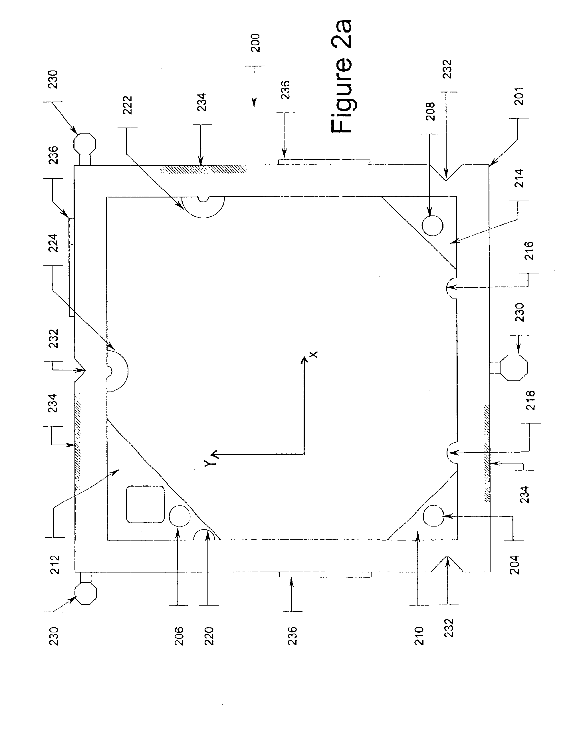
In an exemplary embodiment, a framing structure surrounds the perimeter of the reticle substrate and contacts it at the edge with precision guidance surfaces as the reticle is lowered onto the device. The reticle abuts against conical sections to correct its position and orientation along the plane of its mask surface. Spherical surfaces contact the substrate at its standardized datum reference areas. Near the intersection of the X and Y reference planes, a minimal area of the reticle face comes to rest on a spherical support surface as far away from the reticle mask as possible. This surface completes a tripod of vertical support in conjunction with the conical sections, which maintain contact with the reticle edges only. Secondary and tertiary spherical support surfaces can be provided for vertical support of the other two lateral corners of the reticle face to mitigate reticle tilt while it is being lowered onto the tripod contact points.

Problems solved by technology

Airborne particles and dust that settle on the reticle can cause defects on the wafer.
Small image distortions or displacements in the reticle plane can swamp critical dimension and overlay error budgets.
However, removal of particles from the reticle can cause damage to the reticle because such removal may involve direct contact with the reticle.
The pellicle approach, however, is not well suited for use in extreme-ultraviolet (EUV) applications because there are no materials sufficiently transparent to EUV that can be used to make a pellicle.
In the absence of a pellicle, contaminants will land on the surface of a mask and degrade the quality of the image reflected onto the wafers produced in EUV applications.
Nonetheless, particulate contaminants exist that could adhere to a mask; whether they are airborne in a clean environment or scattering through a vacuum.
In particular, contact spots on a reticle used to hold it and transport it within the lithographic system can generate sub-microscopic fracture particles that can land on the mask as contaminants or debris.
This process is contact-intensive, insufficiently accurate to achieve sub-100 nm alignment accuracy, and can take long enough to impact the productivity of the lithography system.
This process becomes extremely difficult in the case of an EUV lithography system, because of the lack of pellicles and the need to maintain a vacuum environment.
The inventor has found that this additional positioning effort dramatically increases the likelihood of sub-microscopic particle contamination.

Method used


Image

  • Method and apparatus for kinematic registration of a reticle
  • Method and apparatus for kinematic registration of a reticle
  • Method and apparatus for kinematic registration of a reticle

Examples


Embodiment Construction

Embodiments of the present invention provide, among other things, an improved reticle frame and improved methods for mounting reticles. Exemplary embodiments will now be described in detail with reference to the drawings, starting with FIGS. 2a and 2b.

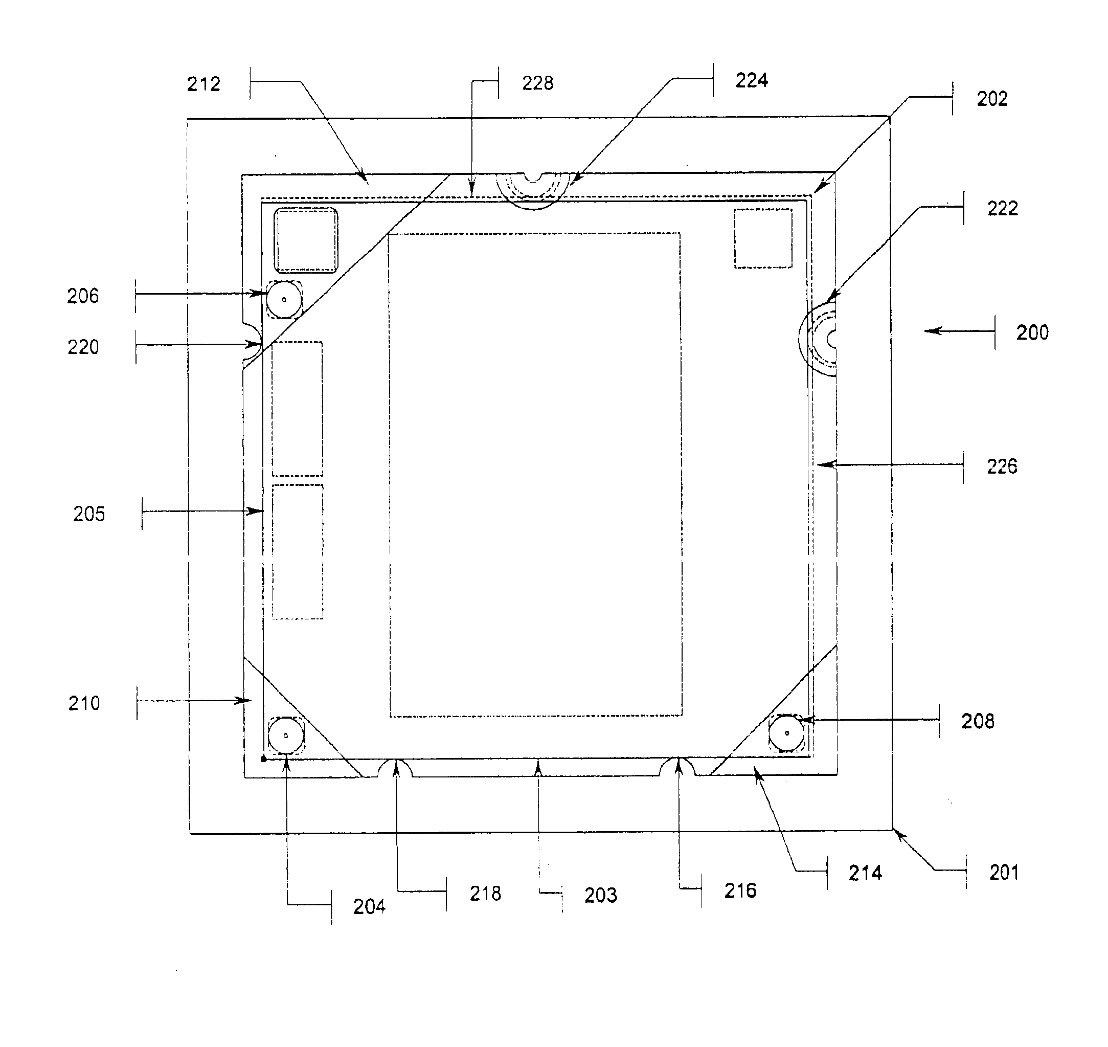
FIG. 2a illustrates a reticle gripping and registration frame 200 according to one embodiment of the present invention. FIG. 2b shows reticle frame 200, generally square in configuration, supporting a reticle 202. Reticle 202 is a flat translucent plate bearing a precision lithography mask having datum or reference sides 203 and 205 and non-datum sides 226 and 228. In this exemplary embodiment, reticle frame 200 comprises a square frame 201, primary vertical mount 204, secondary vertical mount 206, tertiary vertical mount 208, corner plates 210, 212 and 214, horizontal registration surfaces 216, 218 and 220, and angled surfaces 222 and 224.

A pattern or “mask” on the surface of reticle 202 is located on the lower face of reticle 202 at...


PUM


Abstract

An improved reticle frame structure surrounds the perimeter of a reticle substrate and contacts it at the edge with precision guidance surfaces as the reticle is lowered onto the device. In an embodiment, the reticle contacts conical sections that correct its position and orientation along the plane of its mask surface, and spherical surfaces to position the reticle at its standardized datum reference areas. Near the intersection of the X and Y reference planes, a minimal area of the reticle face comes to rest on a spherical mounting surface as far away from the reticle mask as possible. This surface completes a tripod of vertical support in conjunction with the cones, which maintain contact with the reticle edges only. Secondary and tertiary spherical support surfaces can be provided for vertical support of the other two lateral corners of the reticle face to mitigate reticle tilt while it is being lowered onto the tripod contact points.

Description

BACKGROUND OF THE INVENTION1. Field of the InventionThe present invention is generally related to lithography systems, and more particularly, to reticle positioning devices in a lithography system.2. Background ArtLithography is a process used to create features on a surface of a substrate. The substrate can include those used in the manufacture of flat panel displays, circuit boards, various integrated circuits, and the like. A semiconductor wafer, for example, can be used as a substrate to fabricate an integrated circuit.During lithography, a reticle is used to transfer a desired pattern onto a substrate. The reticle can be formed of a material transparent to a lithographic wavelength being used, for example glass in the case of visible light. The reticle can also be formed to reflect a lithographic wavelength being used, for example extreme ultraviolet (EUV) light. The reticle has an image printed on it. The size of the reticle is chosen for the specific system in which it is use...

Claims


Application Information

Patent Timeline
IPC IPC(8): G03F9/00G01D21/00G03B27/62G03F1/14H01L21/02H01L21/027G03F7/20
CPCG03F7/707
Inventor LENOX, RICHARD J.
Owner ASML HLDG NV
Learn More