
Method and apparatus for printing solder paste of different thickness on lands on printed circuit board

a printed circuit board and printed circuit board technology, applied in the direction of inking apparatus, conductive pattern formation, foil printing, etc., can solve the problems of ag solder, difficult to directly use surface-mounting facilities and processes that have used sn—pb solder to solder electronic parts with sn, adversely affecting the environment, etc., to achieve the effect of increasing the amount of solder paste printed

Inactive Publication Date: 2005-02-22
NEC PERSONAL COMPUTERS LTD
View PDF24 Cites 16 Cited by
  • Summary
  • Abstract
  • Description
  • Claims
  • Application Information

AI Technical Summary

Benefits of technology

It is therefore an object of the present invention to provide a printing mask and a printing method which make it possible to increase the applied amount of a solder paste printed on any lands on a PCB without causing the applied solder paste to extend between the lands.
Another object of the present invention is to provide a surface-mounted structural assembly in which electronic parts are reliably joined to lands on a PCB by a solder paste without causing the applied solder paste to extend between the lands, and a method of manufacturing such a surface-mounted structural assembly.
Since the protrusion increases the depth of the through hole defined therein, a layer of solder paste filled in the through hole has an increased thickness. Therefore, the amount of the applied solder paste printed on the lands is increased without increasing the opening area of the through hole. The amount of the applied solder paste printed on any desired land on the printed circuit board can thus be increased reliably without producing a solder bridge or solder balls. The increased amount of the applied solder paste increases solder wettability with respect to through holes and leads in particular, allowing leads passing through the through holes to be joined reliably.
According to the present invention, there is provided a method of manufacturing a surface-mounted structural assembly having an electronic part mounted on a printed circuit board by soldering, comprising the steps of printing a solder paste on a printed circuit board using the printing mask according to the present invention, placing an electronic part on the printed circuit board, and joining the electronic part to the printed circuit board with the solder paste. The method makes it possible to manufacture a surface-mounted structural assembly comprising an electronic part mounted, by soldering, on a printed circuit board having a first land for placing a lead of an electronic part thereon and a second land including a through hole for passing a lead of the electronic part therethrough. In the printing step, since the printing mask is used, a layer of solder paste printed on the second land is thicker than a layer of solder paste printed on the first land. Therefore, the electronic part can reliably be joined to the second land.

Problems solved by technology

However, since the Sn—Pb solder contains Pb that is a toxic heavy metal, it tends to adversely affect the environment if electronic devices including those PCBs are not properly processed after use.
One problem of the Sn—Ag solder is that the melting point of the Sn—Ag solder is about 220° C. that is higher than the melting point of the Sn—Pb solder which is about 183° C. Therefore, it is difficult to directly use surface-mounting facilities and processes that have used the Sn—Pb solder to solder electronic parts with the Sn—Ag solder.
However, the Sn—Zn solder is disadvantageous as compared with the Sn—Pb solder in that Zn is easily oxidizable and makes wetting poor.
If electronic parts are mounted on PCBs with the Sn—Zn solder using the conventional surface-mounting facilities and processes, the Sn—Zn solder is not as reliable as the Sn—Pb solder.
Use of the Sn—Zn solder in the process of printing the solder paste on the PCB and performing reflow soldering poses the following problems: When the solder paste is filled in the through holes in the PCB and through-hole parts are mounted thereon, since the Sn—Zn solder has poor wettability, if the Sn—Zn solder is applied in the same amount as the conventional Sn—Pb, then solder fillets around the leads of the through-hole parts may be small or no solder fillets may be formed around the leads of the through-hole parts on the surface of the PCB opposite to the surface of the PCB that is printed with the solder paste.
Therefore, the through-hole parts may not be well connected to the lands.
However, because the through holes for insertion of the leads of the through-hole parts are defined in adjacent positions in the PCB, if the printing mask with the increased opening areas of the through holes is used, then the applied solder paste is liable to extend between the leads passing through the adjacent through holes.

Method used


Image

  • Method and apparatus for printing solder paste of different thickness on lands on printed circuit board
  • Method and apparatus for printing solder paste of different thickness on lands on printed circuit board
  • Method and apparatus for printing solder paste of different thickness on lands on printed circuit board

Examples


Embodiment Construction

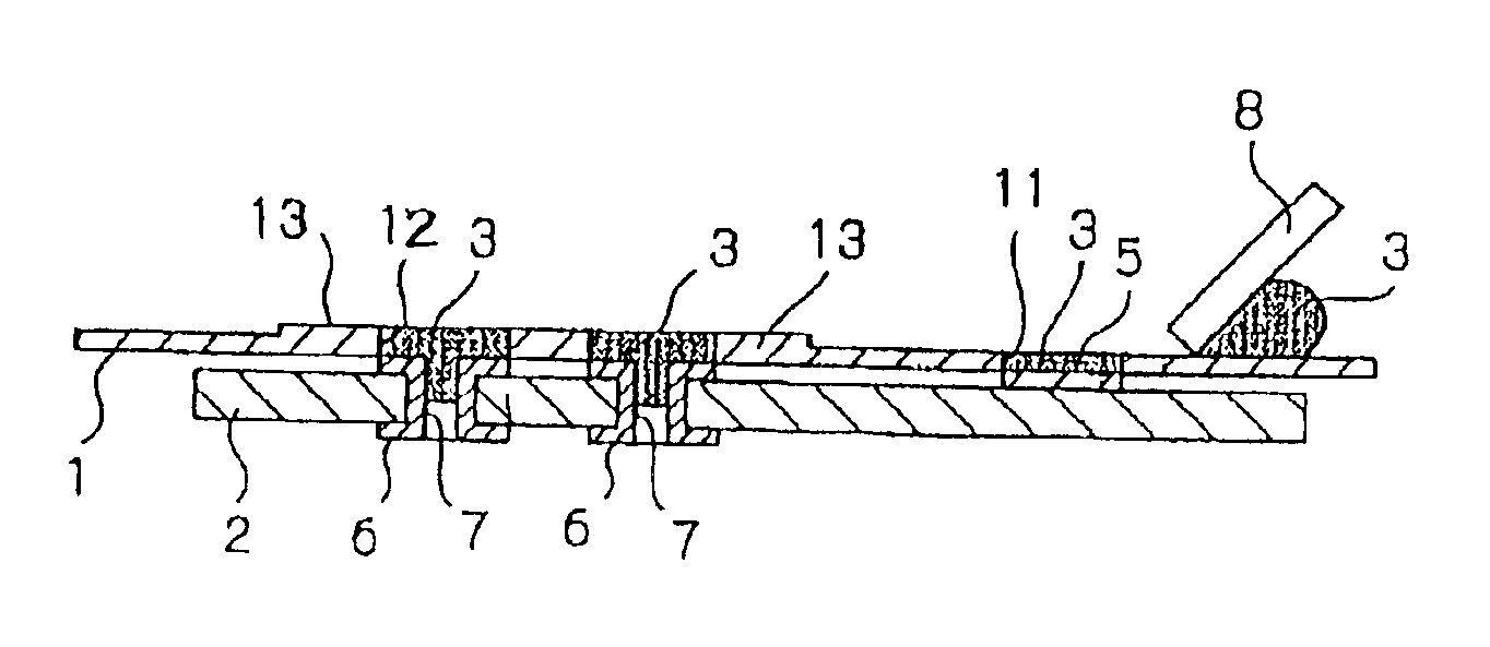
PCB 2 (see FIGS. 5A, 5B, 5C and 6) which will be printed with a solder paste using printing mask 1 according to an embodiment of the present invention as shown in FIGS. 3 and 4 has a plurality of first lands 5 for mounting surface-mount electronic parts and a plurality of second lands 6 for mounting through-hole parts whose leads are inserted in through holes in the PCB, first and second lands 5, 6 being located in predetermined positions. Second lands 6 extend between one surface of PCB 2 and the other surface of PCB 2, with through holes 7 defined respectively therein.

As shown in FIGS. 3 and 4, printing mask 1 comprises a thin sheet of metal such as stainless steel or the like. Printing mask 1 has a plurality of first through holes 11 defined therein which correspond to first lands 5 on PCB 2 and a plurality of second through holes 12 defined therein which correspond to second lands 6 on PCB 2. First through holes 11 have a shape and an area which are substantially equal to the sh...


PUM


Abstract

A printing mask has protrusions having through holes defined therein for printing a solder paste on lands on a printed circuit board. The protrusions serve to increase the amount of solder paste filled in the through holes.

Description

BACKGROUND OF THE INVENTION1. Field of the InventionThe present invention relates to a printing mask and a printing method for printing a solder paste on lands on a printed circuit board for mounting various electronic parts thereon, and more particularly to a surface-mounted structural assembly having a printed circuit board with various electronic parts mounted thereon by soldering and a method of manufacturing such a surface-mounted structural assembly.2. Description of the Related ArtIt has heretofore been the customary practice to use soldering to mount electronic parts on a printed circuit board (hereinafter referred to as “PCB”). One example of a process of mounting electronic parts on both surfaces of a PCB by reflow soldering will be described below with reference to FIG. 1 of the accompanying drawings.In step 101, a solder paste is printed on lands on a surface of a PCB using a printing mask having holes which are defined complementarily to the lands. In step 102, surface-...

Claims


Application Information

Patent Timeline
Patent Type & Authority Patents(United States)
IPC IPC(8): H05K3/12H05K3/34B41F15/34
CPCH05K3/1225H05K3/3447H05K3/3484H05K2201/09736H05K3/3463H05K3/3485H05K3/12
Inventor SAKAI, HIROSHISUZUKI, MOTOJIIGARASHI, MAKOTOTANAKA, AKIHIRO
Owner NEC PERSONAL COMPUTERS LTD
Learn More