
Method of manufacturing battery electrode substrate and battery electrode substrate

a battery electrode and substrate technology, applied in the field of manufacturing battery electrode substrates and battery electrode substrates, can solve the problems of deteriorating reactivity of active substances, battery characteristics are inferior, and the active substance is likely to separate and drop there, so as to improve the performance of batteries, and reduce the pitch between pores each formed at the apex of each of the concave portions and convex portions.

Inactive Publication Date: 2005-03-22
KATAYAMA SPECIAL IND
View PDF18 Cites 0 Cited by
  • Summary
  • Abstract
  • Description
  • Claims
  • Application Information

AI Technical Summary

Benefits of technology

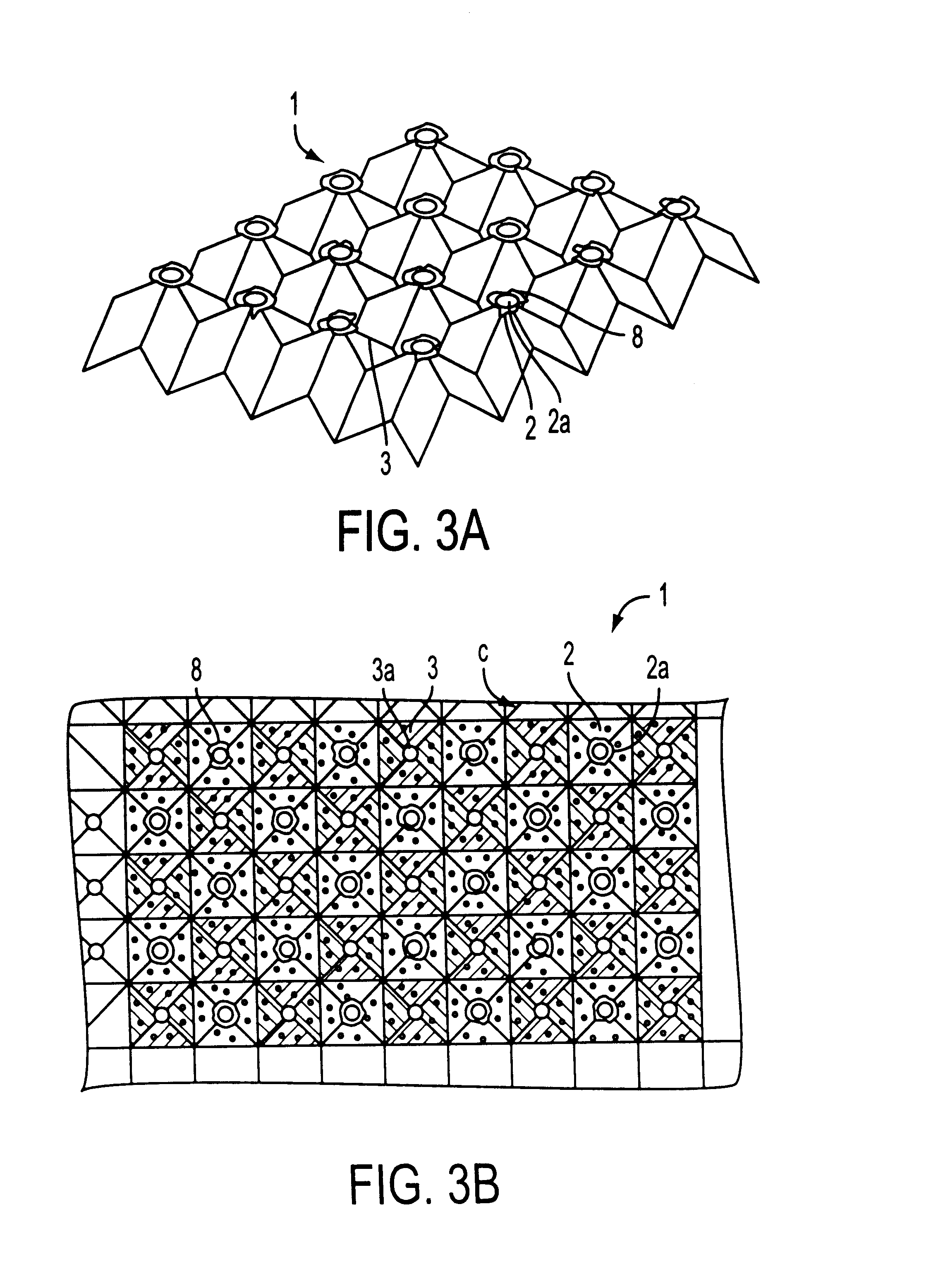
According to the above-described method, by merely passing the metal sheet between a pair of the embossing rotation rollers, comparatively fine concave portions and convex portions can be formed on the entire surface thereof, and at the same time, pores are each formed on the apex of each concave portion and convex portion, and the burr can be projected from the peripheral edge of each pore. Thus, according to the method utilizing the embossing method, compared with the conventional method of forming pores by means of upper and lower dies, the diameter of each pore which is formed on the apex of each concave portion and convex portion and the pitch between the concave portions and that between the convex portions can be allowed to be smaller. Therefore, the pitch between the pores each formed at the apex of each of the concave portions and convex portions can be reduced greatly and the open area ratio, namely, the ratio of the area of the pore to the area of the metal sheet can be allowed to be much larger than that of the metal sheet formed by the conventional method using the dies. Because the burr is generated at the apex of each of the concave portions and convex portions formed densely on the entire surface of the metal sheet, the ratio of the area of the burr to the area of the metal sheet can be allowed to be much higher than that of the metal sheet formed by the conventional method.
As described above, fine concave portions and convex portions are formed on the entire surface of the metal sheet, the pores are each formed on the apex of each concave portion and convex portion, and the burrs are each generated on the periphery of each of the pores. Thus, an active substance which can be applied to the metal sheet can be charged into the concave portions and the convex portions and held by the burrs each generated on the periphery of the apex of each of the concave portions and convex portions. Hence, the charge amount of the active substance can be allowed to be much greater than that of the active substance which is applied to the metal sheet by the conventional method. Further, the active substance can be held by the concave portions and the convex portions reliably because the portions are fine and also held reliably by the burrs because the burrs are present densely on the surface of the metal sheet. Thus, the force of holding the active substance can be allowed to be much greater than the force of holding the active substance which is applied to big pores formed at long pitches by the conventional die. In addition, because the open area ratio is high, ions of the active substance move actively, thus improving the performance of a battery.
As the center plate sandwiched between the upper and lower plates, it is possible to use the plate manufactured by the first method such that it has a great thickness because of concave portions and convex portions formed thereon or the plate manufactured by the third method such that it has a great thickness because of burrs projected from both sides thereof so as to increase the charge amount of the active substance.
In particular, because the plate manufactured by the first method has fine concave portions and convex portions densely, the charge amount of the active substance can be increased and the active substance-holding force can be increased by filling it into the spaces surrounded with the concave portions and convex portions. Even one metal sheet has an increased application amount of the active substance. Thus, a plate consisting of a plurality of the metal sheets which are layered one upon another can be charged with more active substance. Further, the thickness of the plate for a battery electrode can be easily adjusted by merely adjusting the number of metal sheets which are layered one upon another. Thus, it is possible to provide the plate for a battery electrode which can be charged with a necessary amount of the active substance.

Problems solved by technology

In particular, if they have large pores formed thereon, the active substance is likely to separate and drop therefrom during the manufacture and use of an electrode.
But when a large amount of binder is added to the active substance, the reactivity of the active substance deteriorates, and thus the battery characteristic is inferior.
Thus, the foamed porous metal material has a low electricity-collecting performance, thus being incapable of accomplishing a rapid electric charge or discharge when a rapid electric charge or discharge is required.
Thus, it is difficult to improve the characteristic of the battery.
Further, it is difficult to form many fine pores on the entire surface of the metal plate or the metal foil by reducing the diameter of each pore and the pitch between the pores.
Therefore, even though the burr is formed on the periphery of each pore, the burr has a low occupation percentage and an insufficient active substance-holding force.
Thus, these electrodes cause batteries to have inferior performance.
But it is technically very difficult and very costly to form the pores by a pair of upper and lower dies as described above.
Furthermore, only one metal plate having burrs formed thereon does not allow the application amount of the active substance to be increased so much.

Method used


Image

  • Method of manufacturing battery electrode substrate and battery electrode substrate
  • Method of manufacturing battery electrode substrate and battery electrode substrate
  • Method of manufacturing battery electrode substrate and battery electrode substrate

Examples


Embodiment Construction

The embodiments of the present invention will be described below with reference to drawings.

FIGS. 1 through 5 show the first embodiment of the present invention. A plate (S) for a battery electrode of the first embodiment is constructed by layering a large number of metal sheets 1 each of which consists of a nickel foil having a thickness 10 μm-100 μm (15 μm in this embodiment) and which has concave portions and convex portions formed on its entire surface by embossing the sheet.

As shown in FIG. 2, the method of manufacturing each of the above-described metal sheets 1 is carried out by passing a thin flat metal sheet 1′ between embossing rolls 20A and 20B and between the embossing roll 20B and an embossing roll 20C. In the above-described embossing rolls 20A, 20B and 20C, pyramidal fine convex portions 21 are densely formed on the entire outer surface thereof, and pyramidal concave portions 22 are formed between the convex portions 21. Initially, when the metal sheet 1′ is passed be...


PUM


Abstract

Concave portions and convex portion are formed on a peripheral surface of a thin metal sheet by applying a pressing force thereto while the metal sheet is being embossed; pores are each formed on an apex of each of the concave portions and convex portions and burrs each projecting outward from a peripheral edge of each of the pores are generated by the pressing force, the metal sheets having the concave portions and convex portions formed thereon are layered on each other; the burr at the apex of each convex portion of a lower-layer metal sheet is interlocked with the burr at the apex of each concave portion of a upper-layer metal sheet adjacent to the lower-layer metal sheet to integrate the metal sheets with each other; and an active substance is charged into spaces between the upper-layer sheet and the lower-layer metal sheet through and aperture at the apex of each of the concave portions and convex portions.

Description

1. Technical FieldThe present invention relates to a method of manufacturing a plate for a battery electrode and the plate for a battery electrode manufactured by the method, and more particularly to the plate for an electrode which is preferably used for a supply battery of an electric car because of a great thickness thereof to increase the amount of an active substance to be applied thereto and because of a preferable contact thereof with the active substance applied thereto to prevent it from dropping therefrom.2. Background ArtHeretofore, generally, as the plate of an electrode for using a positive electrode and a negative electrode of a nickel / hydrogen battery, a nickel / cadmium battery or the like, principally, a pore-formed nickel-plated steel plate (hereinafter referred to as punching metal) formed by plating an iron plate on which pores are formed by punching is used. An active substance is applied to the punching metal to form the electrode. In the case of a cylindrical ba...

Claims


Application Information

Patent Timeline
IPC IPC(8): B21D31/04B21D31/00H01M4/70H01M4/82H01M4/72H01M4/64H01M4/74H01M4/66
CPCB21D31/04H01M4/70H01M4/742H01M4/82H01M4/74Y10T29/10Y02E60/10H01M4/64
Inventor SUGIKAWA, HIROFUMI
Owner KATAYAMA SPECIAL IND
Learn More