
Back washing type micropore filtering device

A microporous filtration and backwashing technology, which is applied to fixed filter element filters, filtration separation, membrane filters, etc., can solve the problems of increased enterprise costs, frequent replacement of filter screens, etc., to increase application times and reduce cleaning time , the effect of simple process

Pending Publication Date: 2018-08-28
安庆市鑫富化工有限责任公司
View PDF0 Cites 0 Cited by
  • Summary
  • Abstract
  • Description
  • Claims
  • Application Information

AI Technical Summary

Problems solved by technology

[0003] The technical problem to be solved by the present invention is to provide a backwashable microporous filter device with simple operation, high filtration efficiency, and short filter screen / core cleaning time, which solves the problem that existing filter devices need to frequently replace the filter screen and cause The problem of increased business costs

Method used


Image

  • Back washing type micropore filtering device
  • Back washing type micropore filtering device
  • Back washing type micropore filtering device

Examples


Embodiment 1

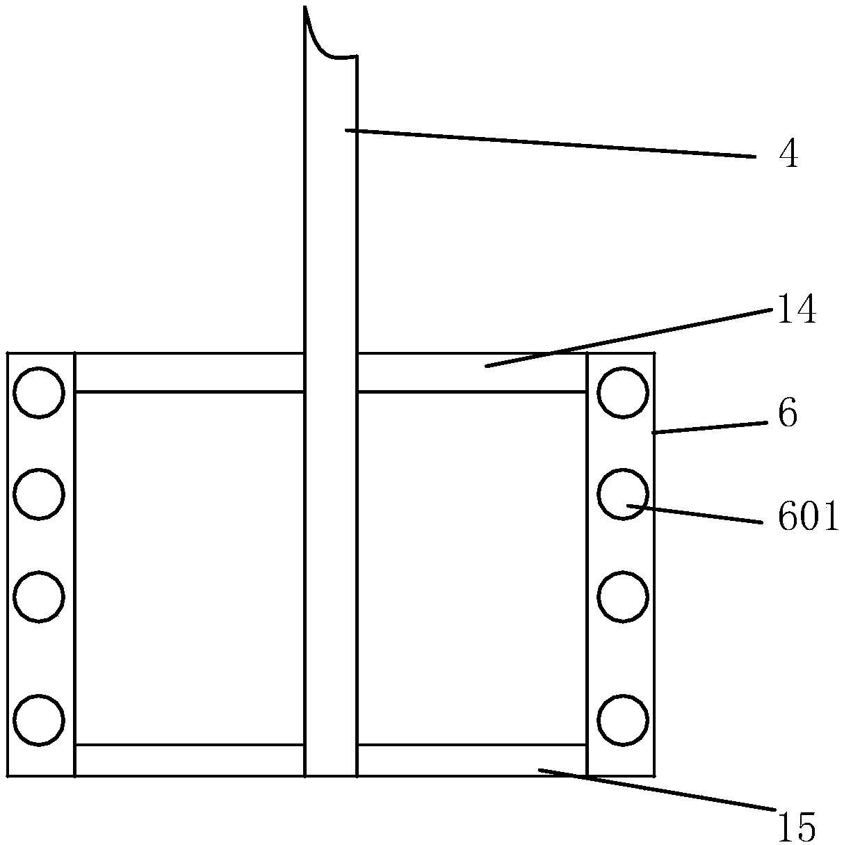
[0020] Such as figure 1 , figure 2 , image 3 As shown, a backwashing microporous filter device includes a housing 5 and a discharge port 18 arranged at the bottom of the housing 5 and a feed inlet 13 arranged on the left side of the top opening of the housing 5, and the opening of the housing 5 The top bolt is connected to the top cover 17, the top of the top cover 17 is installed with a bracket 2 by welding, the top of the bracket 2 is fixedly connected to the deceleration motor 1, and the output end of the deceleration motor 1 is rotationally connected to one end of the rotating shaft 4 through the coupling 3, The other end of the rotating shaft 4 extends into the housing 5 through the top cover 17, and the bottom of the other end of the rotating shaft 4 is sequentially welded to the first connecting rod 14 and the second connecting rod 15 from top to bottom. Both ends of the first connecting rod 14 are The two ends of the second connecting rod 15 are vertically connecte...

Embodiment 2

[0023] Such as figure 2 , image 3 , Figure 4 , Figure 5 As shown, a backwashing microporous filter device includes a housing 5 and a discharge port 18 arranged at the bottom of the housing 5 and a feed inlet 13 arranged on the left side of the top opening of the housing 5, and the opening of the housing 5 The top bolt is connected to the top cover 17, the top of the top cover 17 is installed with a bracket 2 by welding, the top of the bracket 2 is fixedly connected to the deceleration motor 1, and the output end of the deceleration motor 1 is rotationally connected to one end of the rotating shaft 4 through the coupling 3, The other end of the rotating shaft 4 extends into the housing 5 through the top cover 17, and the bottom of the other end of the rotating shaft 4 is sequentially welded to the first connecting rod 14 and the second connecting rod 15 from top to bottom. Both ends of the first connecting rod 14 are The two ends of the second connecting rod 15 are verti...


PUM


Abstract

The invention discloses a back washing type micropore filtering device. The back washing type micropore filtering device comprises a shell, a discharge hole formed in the bottom of the shell and a feeding hole formed in the left side of an opening in the top of the shell, wherein the top of the opening of the shell is in bolted connection with a top cover; a support is mounted on the top of the top cover in a welding manner; the top end of the support is fixedly connected to a gear motor; the output end of the gear motor is rotatably connected with one end of a rotating shaft through a coupler; the other end of the rotating shaft penetrates through the top cover to extend to the interior of the shell; a first connecting rod and a second connecting rod are welded at the bottom of the otherend of the rotating shaft from top to bottom in sequence; and two ends of the first connecting rod are vertically connected with two ends of the second connecting rod through brushing boards respectively. The back washing type micropore filtering device is simple in structure, practical and convenient, and has the characteristics of short filtration effect and short filtration time.

Description

Technical field: [0001] The invention relates to the technical field of filtering equipment, in particular to a backwashing microporous filtering device. Background technique: [0002] The filter is an indispensable device on the conveying medium pipeline, and is usually installed at the inlet end of other equipment such as pressure reducing valves, pressure relief valves, and water level valves. The solid-liquid mixture to be treated passes through the filter screen / core of the filter, and its impurities are blocked. When cleaning is required, the detachable filter screen / core needs to be taken out and reinstalled after processing. Repeated disassembly and installation of the filter screen / core will affect the trial life, increase the production cost of the enterprise, and increase the labor intensity of the workers. Aiming at the above problems, the present invention introduces a backwashing microporous filter device, through the backwashing device, the surface impurities...

Claims


Application Information

Patent Timeline
Patent Type & Authority Applications(China)
IPC IPC(8): B01D29/11B01D29/50B01D29/64B01D29/68
CPCB01D29/11B01D29/50B01D29/6415B01D29/68B01D2201/345
Inventor 胡益辉白彦兵朱松青
Owner 安庆市鑫富化工有限责任公司
Learn More