
Programmable diffraction grating sensor

Inactive Publication Date: 2005-02-08
HONEYWELL INT INC
View PDF7 Cites 9 Cited by
  • Summary
  • Abstract
  • Description
  • Claims
  • Application Information

AI Technical Summary

Benefits of technology

The present invention overcomes one or more of these or other problems by using a programmable diffraction grating between the light source and the sample cell rather than between the sample cell and the detector as is done in the prior art. Therefore, the programmable diffraction grating is part of the light source according to the present invention rather than part of the detector according to the prior art. A significant advantage of the invention is that it allows simple, sensitive photoacoustic detection.
As noted in prior art reference U.S. Pat. No. 5,933,245, herein incorporated by reference, photoacoustic measurement is based on the tendency of molecules, when exposed to certain frequencies of radiant energy (e.g. infrared radiant energy), to absorb the energy and reach higher levels of molecular vibration and rotation, thereby to reach a higher temperature and pressure. When the radiant energy is amplitude modulated, the resulting fluctuations in energy available for absorption produce corresponding temperature and pressure fluctuations.
A sensitive microphone can be used to generate an electrical output representing the pressure fluctuations. The amplitudes of the acoustic signal and resulting electrical output are proportional to the intensity of the radiation and the concentration value of the absorbing gas. Accordingly, given a constant amplitude of radiant energy illumination, the electrical output can be detected at the modulating frequency to provide a concentration value proportional to an absorbing amount of the gas. Further, the proportional relationship with light source intensity allows the user to increase sensitivity by increasing light source intensity. Thus the devices are well suited for measuring small concentration values of gases (ppm, i.e., parts-per-million range), especially as compared to sensors that rely on measurement of transmitted radiant energy.
A variety of these devices are known, e.g. see U.S. Pat. No. 4,557,603 (Oehler et al), U.S. Pat. No. 4,818,882 (Nexo et al), and U.S. Pat. No. 4,866,681 (Fertig), all of which are herein incorporated by reference. The devices have several components in common. In particular, a laser or other energy source produces radiant energy which is modulated either thermally (power on / off) or with a chopping device.
The modulated energy is provided to a cell containing a gas or gas mixture that absorbs the radiant energy, leading to temperature fluctuations in the gas that track the modulation frequency. Temperature is not sensed directly. Rather, pressure fluctuations that accompany the temperature fluctuations are detected by a sensitive microphone in the cell. The microphone output is detected at the modulation frequency, to provide an electrical signal proportional to the gas concentration.
Further discussion on these devices may be found in “Opto-Acoustic Spectroscopy”, Dewey, Jr., Optical Engineering, November / December 1974, vol. 13, No. 6, pp. 483-488; “A Simple Device For Trace Gas Analyses In The Atmosphere”, Journal De Physique, October 1983, pp. 587-591; “A simple photoacoustic gas-detection system”, Rapport de la reunion d'autonne de la Societe Suisse de Physique, vol. 54, 1981, pp. 631-635; “Photoacoustics and Photoacoustic Spectroscopy,” A. Rosencwaig, published by John Wiley&Sons(1980); and “Optoacoustic Spectroscopy and Detection,” Y-H Pao, editor, published by Academic Press (1980, all herein incorporated by reference.

Problems solved by technology

The need for including a sample of a target substance limits the usefulness of the correlation spectrometer.
It is awkward to change target substances.
Moreover, the correlation spectrometry technique is impractical for transient substances because the target substance is unstable.
This correlation spectroscopy technique is also impractical for detection of highly toxic substances because the use of a sample target substance is hazardous.
Therefore, known correlation spectrometers are, for the most part, still limited to the analysis of one or, in some instances, a very few substances because some form of mechanical programming is incorporated into the correlation spectrometers in order to provide the target signature.
These filters are typically limited to utilize only a single one of the many spectral lines which characterize the target substance, and thus may fail to accurately distinguish the desired target substance from other substances.
Thus, prior art correlation spectrometers typically are preprogrammed for the analysis of a very limited number of substances, are not easily reprogrammed for the analysis of other substances, may not accurately distinguish the target substance, and are not practical for analysis of some classes of substances.
Known correlation spectrometers suffer from other drawbacks: expensive infrared detectors may have to be cooled well below room temperature to achieve the required sensitivity.

Method used


Image

  • Programmable diffraction grating sensor
  • Programmable diffraction grating sensor
  • Programmable diffraction grating sensor

Examples


Embodiment Construction

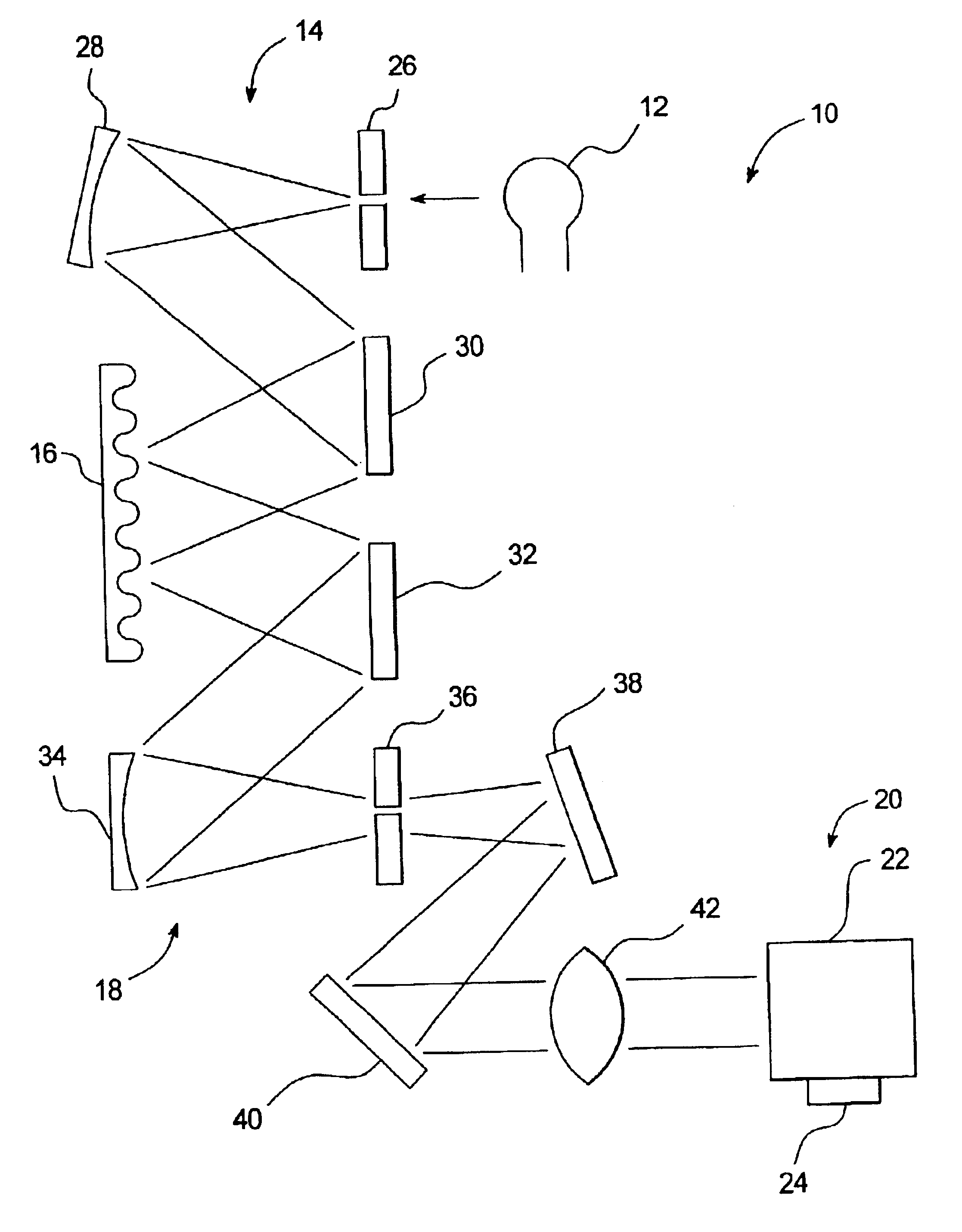
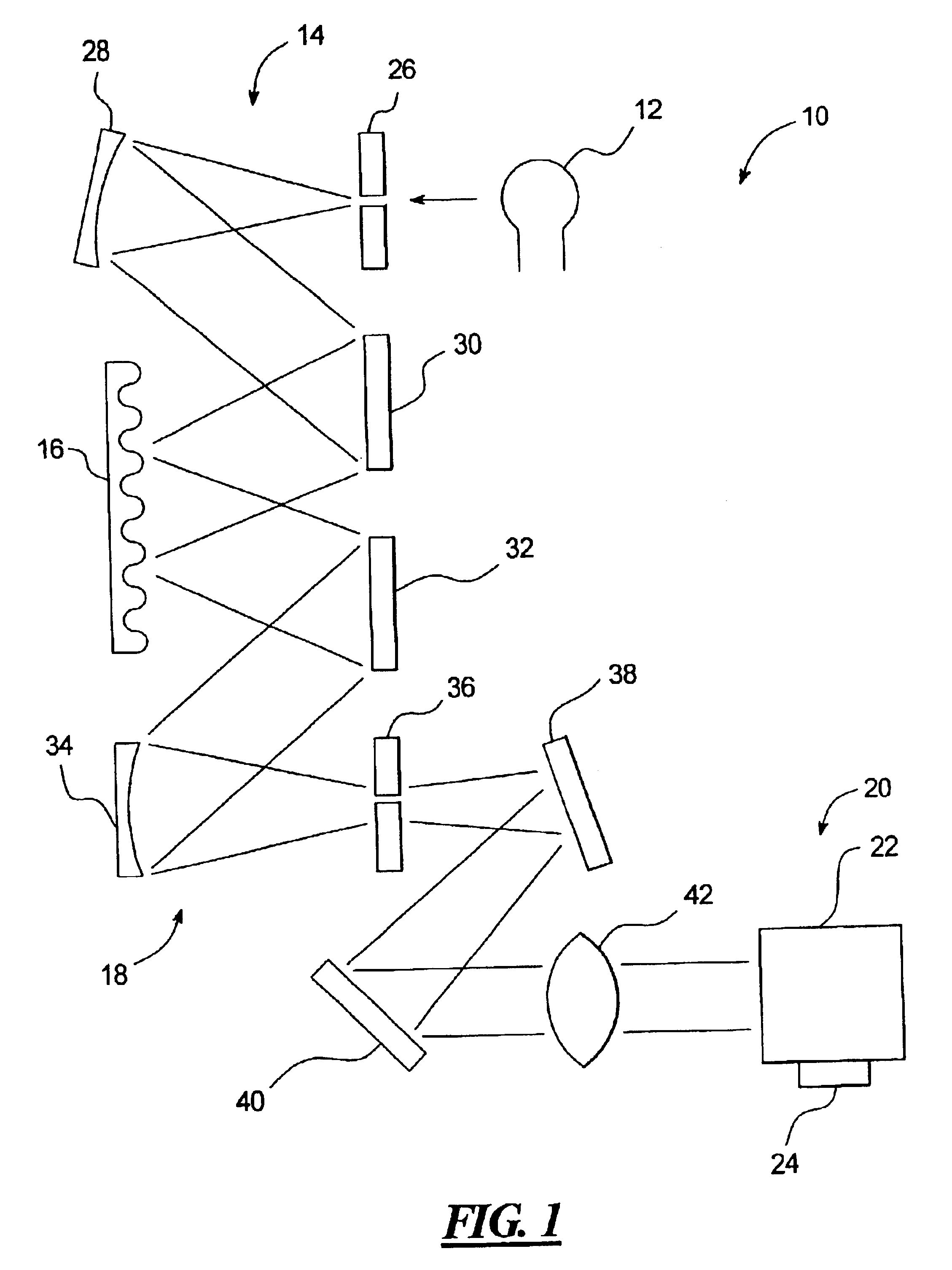
A programmable substance detector 10 according to an embodiment of the present invention is shown in FIG. 1 and includes a light source 12. The light source 12, for example, may be a source of infrared light. The light from the light source 12 is directed along a first light path 14 to a programmable diffraction grating 16. The programmable diffraction grating 16 is controlled so as to diffract light having a multi-line spectra characteristic of a target substance. The programmable diffraction grating 16 also suitably modulates the light from the light source 12 at a predetermined modulation frequency. The diffracted and modulated light from the programmable diffraction grating 16 is supplied through a second light path 18 to a sample cell 20 holding a sample of an unknown substance, such as a gas, to be identified. The modulation imposed by the programmable diffraction grating 16 may be, for example, amplitude modulation. Alternatively, the modulation may be imposed by a separate m...


PUM


Abstract

A programmable substance detector includes a light source, a sample cell, a programmable diffraction grating positioned to receive light from the light source and to direct diffracted light to the sample cell, and a detector associated with the cell to detect a match between a characteristic of the diffracted light and a corresponding characteristic of a substance within the cell.

Description

TECHNICAL FIELD OF THE INVENTIONThe present invention relates to a sensor, such as a photoacoustic sensor, that may be programmed to detect selected substances such as gases.BACKGROUND OF THE INVENTIONA spectrometer can be used to qualitatively and / or quantitatively analyze substances such as gases, liquids, and solids according to a spectral signature characteristic of each substance. A correlation spectrometer analyzes a sample of an unknown substance by first passing broadband light through the unknown substance so that the broadband light picks up the spectral signature of the unknown substance, and by then passing the light containing the spectral signature through a sample of a known target (reference) substance so that the transmitted light picks up the spectral signature of the target substance. The two spectral signatures are thereby correlated. If the correlation is sufficiently high, it may be assumed that the unknown substance and the target substance are the same.The ne...

Claims


Application Information

Patent Timeline
IPC IPC(8): G01J3/28G01J3/457G01N21/17G01N29/24
CPCG01J3/28G01J3/457G01N21/1702G01N29/2425G01N2201/0691G01N2021/1725G01N2201/0635
Inventor HOCKER, G. BENJAMIN
Owner HONEYWELL INT INC
Learn More