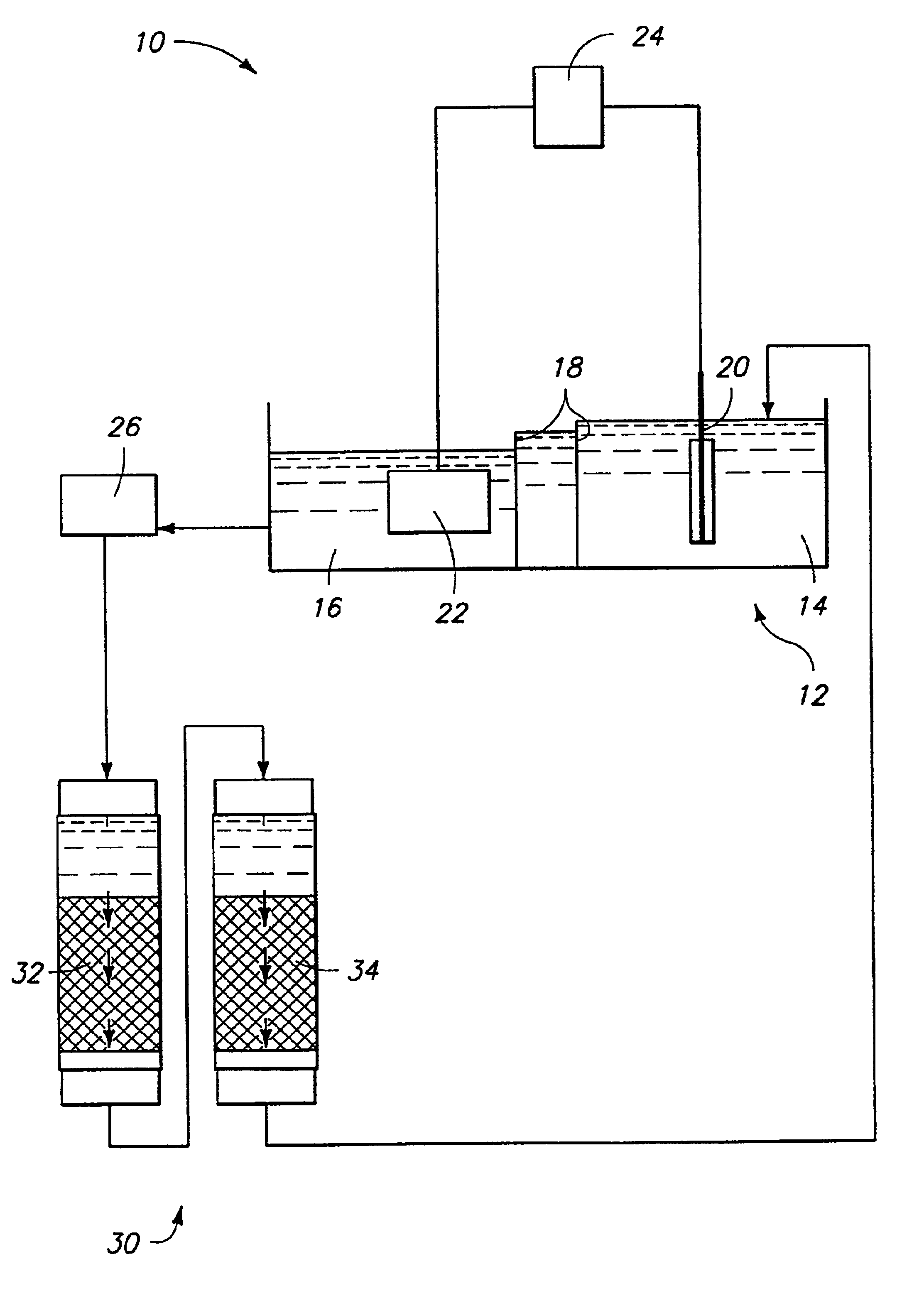
Apparatus for processing metals
a technology for processing apparatus and metals, applied in the direction of electrochemical machining apparatus, crystal growth process, chemical/physical process, etc., can solve the problems of difficult separation of cobalt and nickel, alkali metals (such as na and k),
- Summary
- Abstract
- Description
- Claims
- Application Information
AI Technical Summary
Benefits of technology
Problems solved by technology
Method used
Image

Examples
example 1
Electrolytic Formation of Cobalt
A sample of 1472 lbs of CoSO4·7H2O is dissolved into 370 gallons of water at room temperature while stirring. Again while stirring, the pH of the cobalt sulfate solution is adjusted to 2 by adding 2.44 gallons of 98% sulfuric acid, ACS grade. The solution is added to a divided electrolysis tank and heated to 122° F. Circulation is started to the ion exchange tanks, which contain 5 cubic feet of resin, and a flow through the tanks is at a rate of 0.5 GPM. The cobalt sulfate solution is analyzed and found to contain 80 to 90 g / L Co, 3 to 4 mg / L Fe, and 1 to 2 mg / L Ni, and the pH is 2. Electrolysis is run at constant current of 300A and the voltage observed to fall from 9V to 5V over the 216 hour run. Cathodes are 99.95% Co sheet, and run at a current density of 18 A / ft2. About 116 lbs of cobalt is harvested, which relates to a cathodic current efficiency of 74%. The analysis of the deposit is shown in Table 1 as the “high purity cathode”. Also shown in ...
example 2
CoCl2 System
Cobalt powder of a purity 3N8 (99.98%), Powder A, and 2N7 (99.7%), Powder B, is dissolved in HCl (35-38%, by weight, in water). The solution is then heated to about 80° C., while stirring, for about 10 hours. Solid CoCl2.6H2O is dissolved by adding 2 liters of deionized water and stirring at about 50° C. for about 8 hours. More deionized water is then added to get a final solution volume of about 5 liters.
A plastic tube of 0.953 cm inside diameter and 120 cm length, connected on one end with a reducer, is used as an ion exchange column. Glass wool is used as screen material. The tube is filled with about 42.6 ml Dowex M-4195 anion exchange resin, with an average size of 20-50 mesh. Prior to loading, the resin is conditioned by passing 2 bed volumes (BV) of HCl solution through it at a flow rate of about 15 BV / Hr. The pH value of the HCl solution is the same as that of the feed solution. A typical experiment comprises (1) loading the resin by pumping cobalt chloride solut...
example 3
Fe-removal
Fe can be a major impurity element in cobalt. Like Ni, it can influence the pass-through flux of cobalt sputtering targets, and accordingly is preferably minimized. Although the resin used in the invention has the capability to absorb a certain amount of Fe, additional Fe removal steps are desired when Fe content in the raw cobalt is high. Different methods can be used for Fe removal: 1) Fe(OH)3 precipitation; 2) solvent extraction; and 3) an additional selective ion exchange; etc. In a particular embodiment, this invention has successfully integrated Fe(OH)3 precipitation into the cobalt refining process to handle excessive Fe impurities.
For Fe(OH)3 precipitation, air or oxygen gas is blown into the impure CoSO4 or CoCl2 solution during stirring for a certain time to oxidize the Fe2+ ions to Fe3+ ions. NaOH is then added to the CoSO4 or CoCl2 solution to change its pH to about 4. Fe(OH)3 crystallizes at such pH because of its low solubility. After most of the Fe(OH)3 has ...
PUM
| Property | Measurement | Unit |
|---|---|---|
| Temperature | aaaaa | aaaaa |
| Fraction | aaaaa | aaaaa |
| Fraction | aaaaa | aaaaa |
Abstract
Description
Claims
Application Information
 - R&D
- Intellectual Property
- Life Sciences
- Materials
- Tech Scout
- Unparalleled Data Quality
- Higher Quality Content
- 60% Fewer Hallucinations
Browse by: Latest US Patents, China's latest patents, Technical Efficacy Thesaurus, Application Domain, Technology Topic, Popular Technical Reports.
© 2025 PatSnap. All rights reserved.Legal|Privacy policy|Modern Slavery Act Transparency Statement|Sitemap|About US| Contact US: help@patsnap.com