Card-edge connector and card member

a card-edge electrode and connector technology, applied in the direction of printed circuit aspects, coupling device connections, instruments, etc., can solve the problems of failure to establish and the inability of card-edge electrodes to extend to the edge of the circuit board

Inactive Publication Date: 2005-02-08
NEC CORP
View PDF7 Cites 15 Cited by
  • Summary
  • Abstract
  • Description
  • Claims
  • Application Information

AI Technical Summary

Benefits of technology

It is an object of the present invention to provide a card edge connector allowing a minimum of defective contact to occur and allowing a minimum of impurities to deposit on the contact points of contacts.

Problems solved by technology

In this respect, the above conventional card-edge connector has the following problems left unsolved.
When the card member is shifted or inclined when inserted into the connector, the contact points of the contacts are shifted from the card-edge electrodes, failing to establish electrical, connection.
Further, the card-edge electrodes cannot be extended to the edge of the circuit board for production reasons.

Method used


Image

  • Card-edge connector and card member
  • Card-edge connector and card member
  • Card-edge connector and card member

Examples


Embodiment Construction

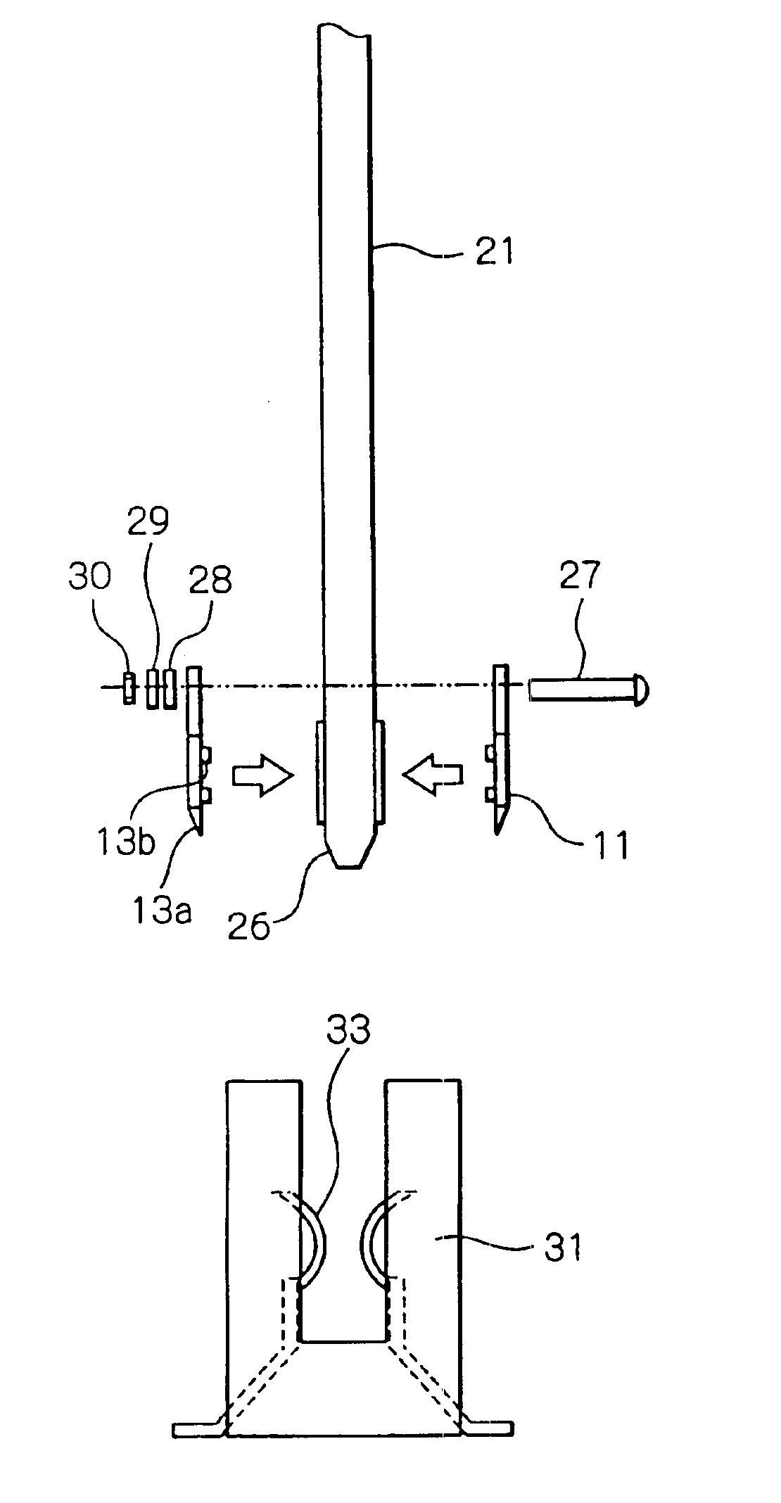
Referring to FIG. 3, a card-edge connector embodying the present invention is shown and generally designated by the reference numeral 10. As shown, the card-edge connector 10 is made up of a card member 10A and a connector 32B provided on a board, which is affixed to, e.g., an electronic apparatus not shown, the card member 10A includes a printed circuit, not shown, and an electrode portion 10C that adjoins one edge of the card member 10A. An insulation cover 11 is affixed to a circuit board 21 included in the card member 10A.

As shown in FIG. 4, a plurality of card-edge electrodes 24 are arranged in the electrode portion 10C of the circuit board 21 and surrounded by solder resist 25. The edge of the circuit board 21 is formed with a taper 26. The circuit board 21 is formed with holes 22a and 22b for affixing the insulation cover 11 and holes 23a, 23b, 23c and 23d for positioning the insulation cover 11. The card-edge electrodes 24 and taper 26 are formed on both sides of the circuit...


PUM


Abstract

A card-edge connector of the present invention includes a card member including a circuit board and a plurality of card-edge electrodes arranged on the circuit board. A connector is affixed to a stationary board and includes a plurality of contacts corresponding one-to-one to the card-edge electrodes. The card member further includes an insulation cover covering an area where the card-edge electrodes are arranged and formed with a plurality of slots via which the card-edge electrodes each are partly exposed to the outside. When the card member is inserted into the connector, the card-edge electrodes and contacts are electrically connected to each other.

Description

BACKGROUND OF THE INVENTION1. Field of the InventionThe present invention relates to a card-edge connector and a card member for an electronic apparatus and more particularly to a card-edge connector and a card member allowing a minimum of defective contact to occur and allowing a minimum of impurities to deposit on the contact points of contacts.2. Description of the Background ArtA conventional card-edge connector applicable to various electronic apparatuses is generally made up of a card member with a printed circuit board and a connector affixed to a board, which is included in an electronic apparatus. The card member includes a circuit board, a plurality of card-edge electrodes arranged on the circuit board, and solder resist surrounding the card-edge electrodes. The connector includes a housing for receiving the card member and contacts corresponding one-to-one to the card-edge electrodes.The conventional card-edge connector described above is superior in electric characterist...

Claims


Application Information

Patent Timeline
Patent Type & Authority Patents(United States)
IPC IPC(8): H01R13/631H05K1/11G06K7/00H01R13/52H01R13/64
CPCH01R13/631H01R12/721H05K1/117H05K2201/10598
Inventor KAMIYAMANE, SHIN
Owner NEC CORP
Why Eureka
Try Eureka