
High-capacity multimode optical fiber systems

a multi-mode, high-capacity technology, applied in the direction of cladded optical fibre, instruments, optical elements, etc., can solve the problems of reducing the permitted pulse-repetition rate and limiting capacity, increasing the need for higher bandwidth, and invariably accompanied by added fiber loss, so as to achieve the effect of high-capacity operation

Inactive Publication Date: 2005-01-04
FURAKAWA ELECTRIC NORTH AMERICA INC
View PDF7 Cites 19 Cited by
  • Summary
  • Abstract
  • Description
  • Claims
  • Application Information

AI Technical Summary

Benefits of technology

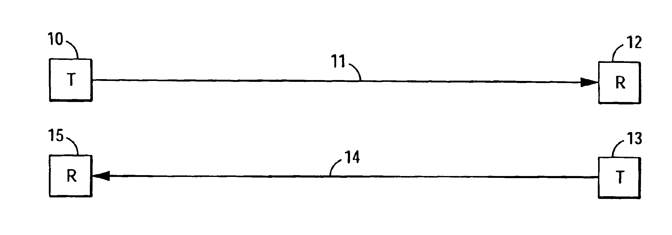
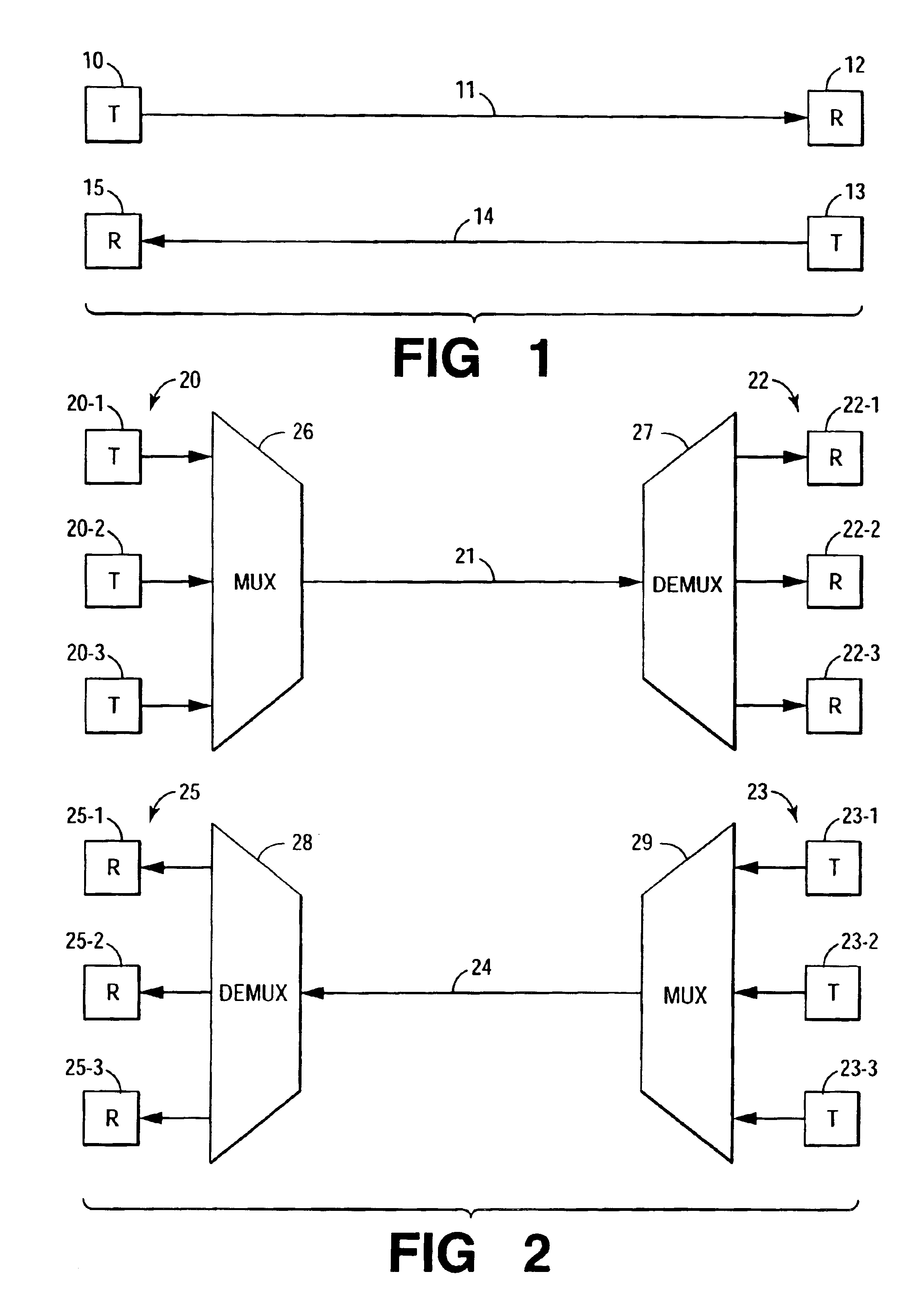
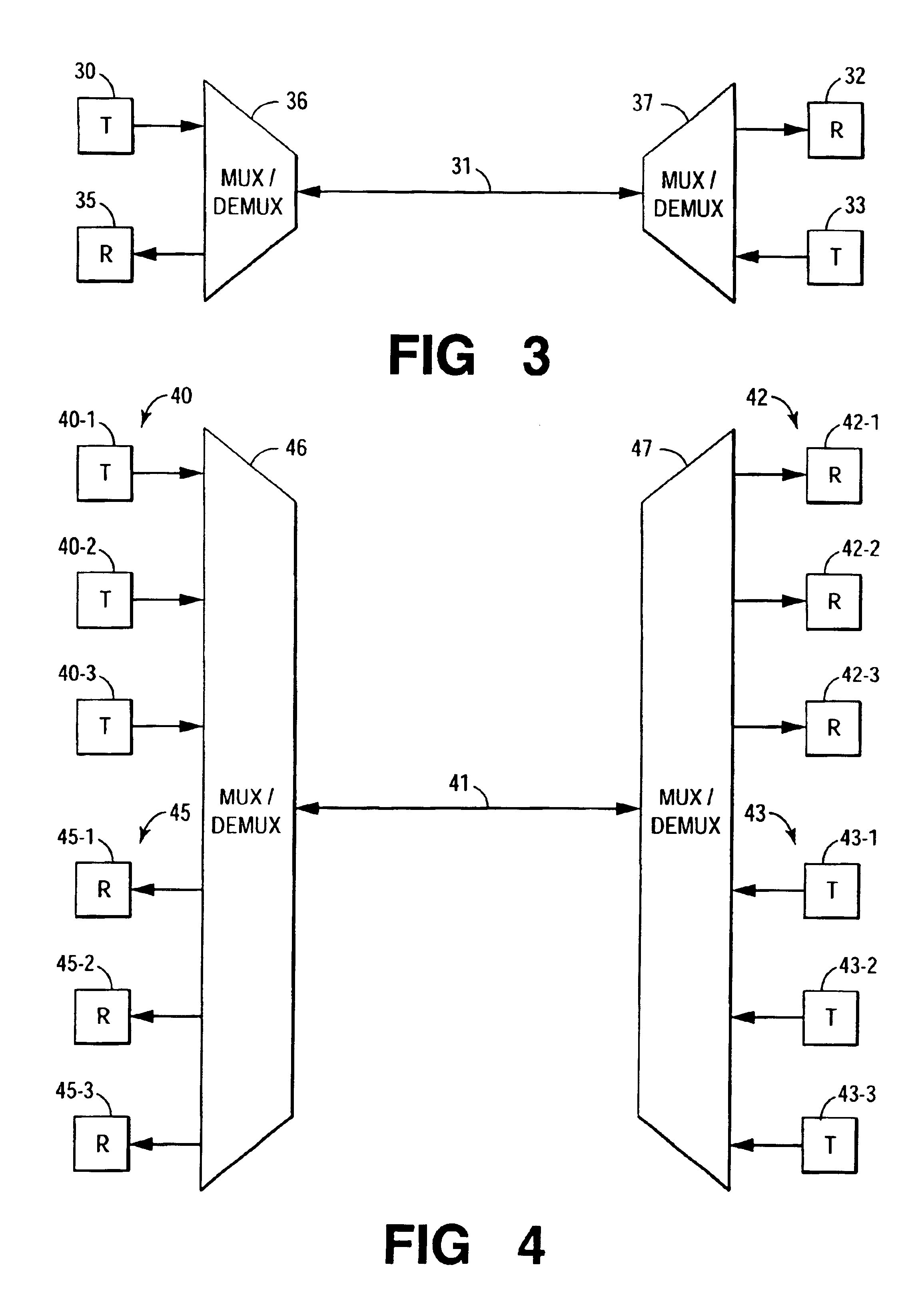
[0025]WDM Local Area Network Systems, with transmission over Enhanced Multimode Fiber (EMF), while realizing attributes of LazrWAVE™ systems, gain from further operational and cost advantages. Included systems, in providing for operation at nominal system wavelength of 850 nm, still satisfy a primary driving force responsible for continuing interest in multimode systems. At the same time, of benefit both in intrabuilding use and in longer-distance LANs—in “Enterprise” or “Campus” systems—included systems may provide for operation at less lossy longer wavelengths, thereby enabling expedient, high-capacity operation over longer transmission distances as well. Such systems, of operating wavelengths ordinarily the province of single-mode systems, may avoid need for frequency-conversion, thereby facilitating interconnection with single-mode long distance systems. At the same time, use of multimode fiber continues to expedite connection with intrabuilding LAN's operating at system wavelength of 850 nm.
[0026]Included systems depend on transmission over Enhanced Multimode Fiber. That fiber—with its perturbation-induced high bandwidth; with its lessened added loss (in the past, associated with the perturbation stream); and with its broad available wavelength range of operation—in accordance with embodiments of the invention, permits systems of greater information capacity than previously realizable with use of multimode fiber.

Problems solved by technology

Growing need for higher bandwidth would not be satisfied because of mode dispersion.
Differing group velocities for the different modes cause pulse spreading, thereby lowering permitted pulse-repetition rate and limiting capacity.
Unfortunately, regardless of the type of perturbation, improvement in bandwidth was invariably accompanied by added fiber loss.

Method used


Image

  • High-capacity multimode optical fiber systems
  • High-capacity multimode optical fiber systems
  • High-capacity multimode optical fiber systems

Examples


Embodiment Construction

[0034]1. General

[0035]The invention takes advantage of operating capabilities generally associated with multimode fiber, with its many economies—with significant cost saving in circuit elements and in installation. LAN systems of the invention, like most now in use, continue to provide for operation at the nominal system wavelength, λs=850 nm. Improved capabilities offered by EMF—notably increased wavelength range of operation—translate, as well, into practical multimode operation in the low-loss 1310 nm and 1550 nm transparency regions of silica-based fiber. CWDM capacities, for channel sets of broad (many nanometer) channel-to-channel separation, offer niche uses with cost advantage over DWDM single-mode systems (which are dependent on closer channel-separation and, in consequence, on more costly circuit components).

[0036]2. The Fiber

[0037]Systems make use of the enhanced multimode fiber (EMF) of the co-pending patent application Ser. No. 10 / 408,076 “Enhanced Multimode Fiber”. EMF...


PUM


Abstract

Multimode optical fiber local area networks, both intrabuilding and interbuilding, are optimized to take advantage of the wide wavelength operating range offered by co-pending patent application Ser. No. 10 / 408,076 “Enhanced Multimode Fiber”—a fiber provided both with: longitudinally spaced perturbations for inducing mode coupling and thereby lessening mode dispersion; and with a radial discontinuity for discouraging conversion of bound-to-cladding-modes and thereby lessening added loss previously associated with induced mode coupling.

Description

FIELD OF THE INVENTION[0002]The field addressed concerns short and medium distance optical fiber communication systems based on multimode fiberlocal area network (LAN) systems, both intrabuilding with system lengths characteristically up to 500 meters, and interbuilding with system lengths of up to approximately 10 kilometers (km).DESCRIPTION OF THE PRIOR ART[0003]Continued dominance of single-mode fiber for long-distance fiber communications is assured. Device development has kept pace with fiber, resulting in DWDM systems with per-fiber capacity of a terabit / sec. See, e.g., A. Kung, et al., “10 Gb / s and 40 Gb / s Ultra-long haul transmission on a common all-Raman single-wideband platform,” 28th European Conference on Optical Communications, paper 1.1.1, Copenhagen, Denmark, Sep. 8-12, 2002. Operation at system wavelength of 1310 nanometers (nm) has largely yielded to operation at 1550 nm. Recent work in reducing the water peak responsible for increased loss at system wavelengths be...

Claims


Application Information

Patent Timeline
IPC IPC(8): G02B6/028G02B6/02H04B10/13H04B10/2581
CPCH04B10/2581G02B6/0288
Inventor WHITE, IAN A.
Owner FURAKAWA ELECTRIC NORTH AMERICA INC
Learn More