Hydrogen supply device

a technology of water supply device and hydrogen supply, which is applied in the direction of lighting and heating apparatus, sustainable manufacturing/processing, and separation processes, etc., can solve the problems of slow temperature increase, large heat resistance, and exhaustion of harmful ingredients such as unburned components in combustion gas into the atmosphere, and achieve the effect of fast activation speed of reforming reaction

Inactive Publication Date: 2005-01-04
DENSO CORP
View PDF13 Cites 9 Cited by
  • Summary
  • Abstract
  • Description
  • Claims
  • Application Information

AI Technical Summary

Benefits of technology

In view of the above-described problem, it is an object of the present invention to provide a hydrogen supply device, in which hydrogen produced from reforming material is supplied to a hydrogen consumption device, having a faster activation speed of reforming reaction at a starting time. Further, to provide a hydrogen supply device that exhausts a limited amount of harmful component of a hydrogen consumption device to the air is another object. Furthermore, it is a further object to provide a compact hydrogen supply device in which moisture is collected from exhaust gas of a hydrogen consumption device and supplied to a CO eliminating section. Moreover, a further object is to provide a compact hydrogen supply device in which impurities other than hydrogen contained in hydrogen rich gas produced in a reforming section is eliminated.
As mentioned above, the first rotary thermal storage is directly heated by high temperature fluid so that temperature thereof is effectively elevated with higher response characteristic. Accordingly, at a starting time of the device, the reforming reaction starts in a shorter time because the catalyst activates more rapidly.
Further, a heat transfer amount per a unit area is larger since the heat exchange between the high and low temperature fluid is not conducted through a conventional isolation wall interposed therebetween and a heat transfer surface itself is heated by the high temperature fluid. Accordingly, heat exchange efficiency is higher and the heat transfer surface for securing the required heat transfer amount is limited to a smaller area so that the device itself becomes more compact.
The combustion gas supply section is provided, preferably, with a combustion fuel supply section for supplying combustion fuel and igniting means for igniting the combustion fuel to produce the combustion gas. As the combustion fuel supply section in which fuel for more rapidly activating the catalyst is supplied and ignited is integrated with the combustion gas supply section in which off gas is supplied, the device is more compact.
It is preferable that an exhaust purification section, which has an exhaust purification body provided with a plenty of exhaust through holes and oxidation catalyst affixed to surfaces of the exhaust through holes, is disposed in the high temperature fluid passage on a downstream side of the common rotary thermal storage. Oxidation catalyst serves to promote an oxidation reaction of surplus oxygen and unreacted components such as CO contained in the reformed gas. The exhaust purification section is further provided with heating means for heating the exhaust purification body for a purpose of faster activation of the catalyst and / or on an upstream side of the exhaust purification body with an adsorbent, which adsorbs harmful components even before the catalyst reaches activating temperature.
Furthermore, the specified material is nitrogen and / or carbon dioxide contained in the reformed gas flowing in the reformed gas passage. Accordingly, hydrogen density of the reformed gas becomes higher.

Problems solved by technology

However, since the combustion heat generated in the combustion chamber indirectly heats the reforming catalyst disposed in the reforming chamber through the isolation wall, heat resistance is larger and temperature increase is slower so that a start timing of the reforming reaction is retarded.
Further, the conventional reforming apparatus has a drawback that a harmful ingredient such as unburned components in the combustion gas is exhausted into the atmosphere without being purified, in particular, at the starting time for activation.
Furthermore, it is disadvantageous to apply the conventional reforming apparatus, which needs a relatively large heat transfer surface or body to secure a required amount of the heat transfer, to a vehicle whose installation space is limited.
Moreover, though the vapor steam reforming reaction, which is an endothermic reaction and needs heat from outside, is useful to obtain rich hydrogen, the conventional heat exchanger is not sufficient enough to supply the heat.
Further, it has a drawback that an amount of gas passing through the passages for fuel reforming increases with higher flowing loss and a driving force for supplying the oxygen increases, too.
Further, the fuel cell, to which hydrogen is supplied, emits exhaust gas containing a large amount of moisture.

Method used


Image

  • Hydrogen supply device
  • Hydrogen supply device
  • Hydrogen supply device

Examples


first embodiment

(First Embodiment)

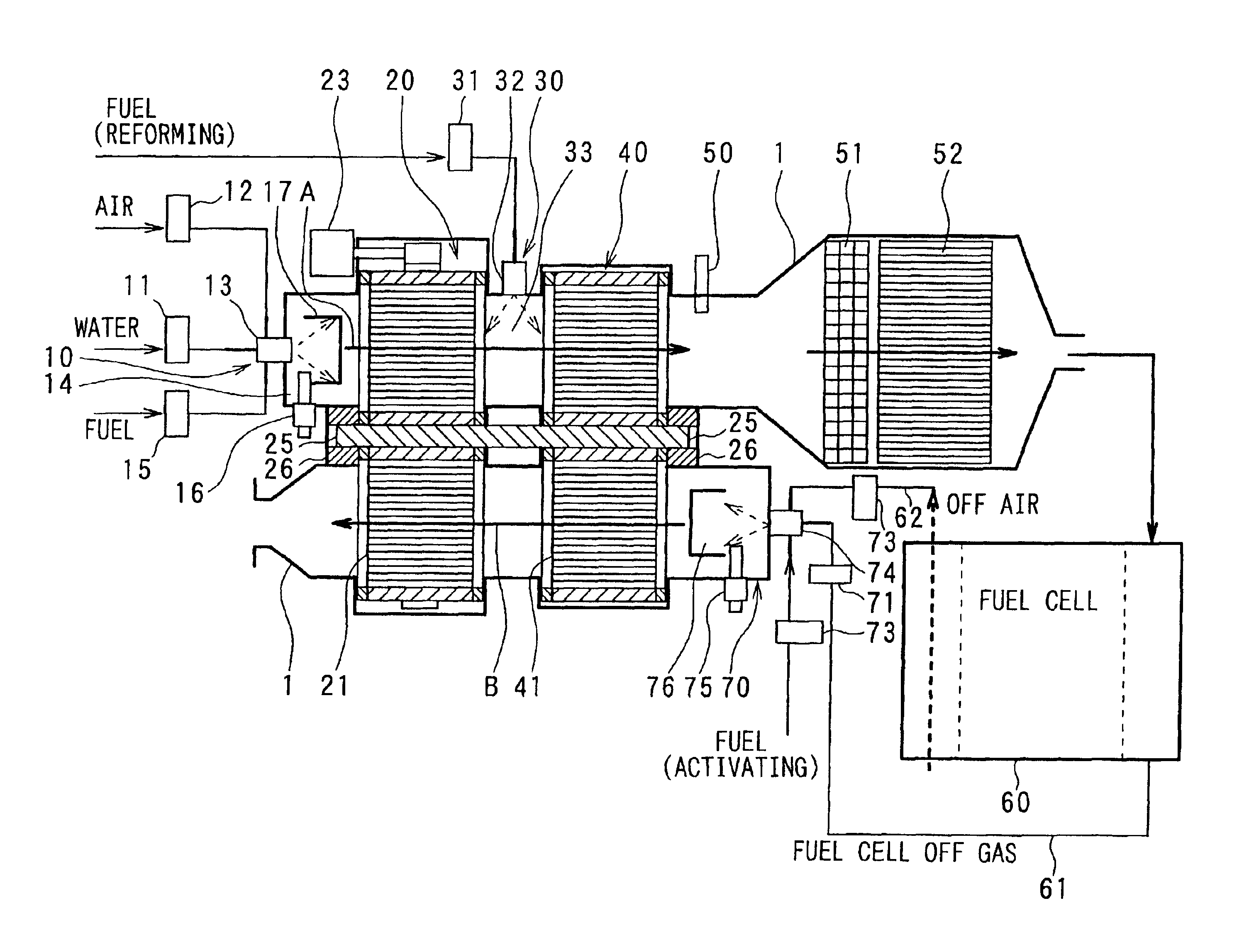
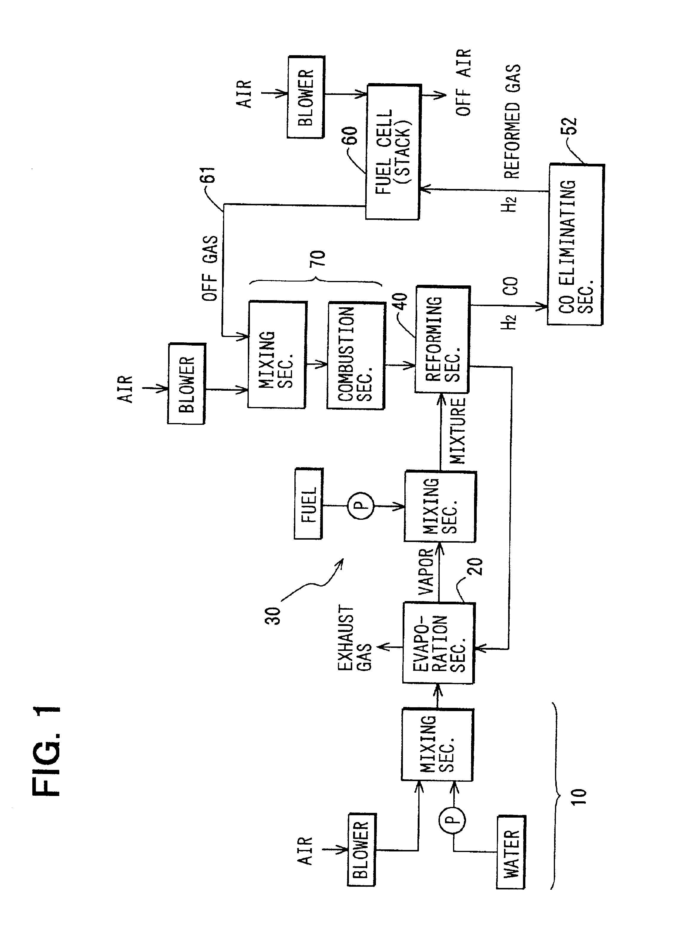
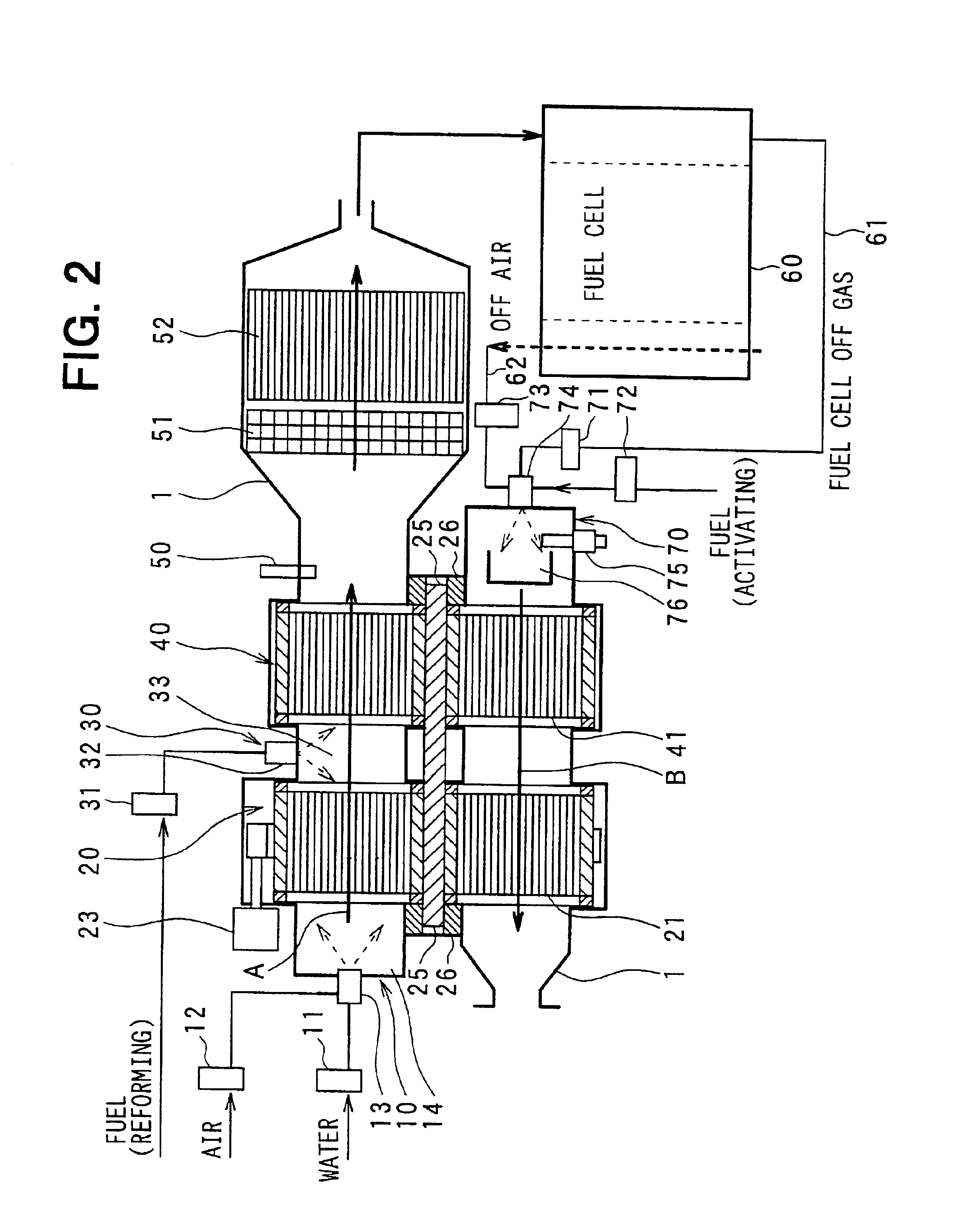
Referring to FIGS. 1 to 6, first embodiment of the present invention will be described. FIG. 1 is a block diagram illustrating a general structure of a hydrogen supply device according to first embodiment. FIG. 2 is a conceptual diagram illustrating an arrangement of components of the hydrogen supply device. The hydrogen supply device according to first embodiment supplies hydrogen to a fuel cell 60, which functions as a hydrogen consumption device.

As shown in FIGS. 1 and 2, the hydrogen supply device according to first embodiment includes a first reforming material supply section 10, an evaporation section 20 (heat exchange evaporation section), a second reforming material supply section 30, a reforming section 40 (heat exchange reforming section), a CO eliminating section 52, and a combustion gas supply section 70 (off gas supply section). Moreover, in the hydrogen supply device, a housing 1 forms a low temperature fluid passage A (a reforming material passage) f...

second embodiment

(Second Embodiment)

Next, referring to FIG. 7, a hydrogen supply device according to a second embodiment of the present invention will be described. When comparing the second embodiment with the above-described first embodiment, configurations are different in a second reforming material supply section 30. The same members as in the above-described first embodiment are denoted with the same reference numerals, and description thereof is omitted.

In a case that the second reforming material (reforming fuel) is supplied to the downstream side of the evaporation section 20 as shown in the first embodiment, it is necessary to effectively mix the first reforming material with the second reforming material in a short time. Accordingly, the second reforming material supply section 30 according to the second embodiment has a mixing section 33 (mixing chamber) in which the first and second reforming material are effectively mixed with each other.

FIG. 7A is an enlarged cross-sectional view of t...

third embodiment

(Third Embodiment)

Referring now to FIG. 8, a third embodiment of the present invention will be described. As shown in FIG. 8, when the third embodiment is compared to the above-described first embodiment described above, it is different in that a fuel flow rate control valve 15, an ignition plug 16 and a combustion chamber 17 are provided in the first reforming material supply section 10. Members similar to the above-described first embodiment will be denoted with the same reference numerals, and description thereof is omitted.

As described above, in a hydrogen supply device according to the third embodiment, the first reforming material supply section 10 is provided with the fuel flow rate control valve 15 for controlling a flow rate of actuation fuel, the ignition plug 16 for igniting the actuation fuel for flame combustion, and the combustion chamber 17 for maintaining the flame combustion.

With the above-described structure, at a starting time of the hydrogen supply device, the fl...


PUM

PropertyMeasurementUnit
temperatureaaaaaaaaaa

Abstract

In the hydrogen supply device for producing and supplying hydrogen to a fuel cell, a reforming section has a rotary thermal storage through which low and high temperature passages pass. Reforming material is supplied to the low temperature fluid passage on an upstream side of the first rotary thermal storage. A combustion gas supply section for generating and supplying a combustion gas is located in the high temperature fluid passage on a downstream side of the first rotary thermal storage. With the hydrogen supply device mentioned above, the first rotary thermal storage rotates to move alternately between the low and high temperature fluid passages so that, in the reforming section, the reforming material flowing in the low temperature fluid passage is catalytically reformed to a reformed gas containing hydrogen upon receiving combustion heat of the combustion gas flowing in the high temperature fluid conduit.

Description

CROSS REFERENCE TO RELATED APPLICATIONThis application is based upon and claims the benefit of priority of Japanese Patent Applications No. 2000-308034 filed on Oct. 6, 2000, No. 2000-395525 filed on Dec. 26, 2000 and No. 2001-190312 filed on Jun. 22, 2001, the contents of which are incorporated herein by reference.BACKGROUND OF THE INVENTION1. Field of the InventionThe present invention relates to a hydrogen supply device for producing hydrogen due to a reforming reaction of reforming material and supplying the produced hydrogen to a hydrogen consumption device.2. Description of Related ArtConventionally, a reforming apparatus, in which hydrogen rich gas is produced by reforming hydrocarbon compound, is well known as a device for supplying hydrogen to a fuel cell. In the reforming apparatus, the hydrogen is produced by reforming material containing hydrocarbon compound due to a catalytic reaction at high temperature (vapor steam reforming reaction). To perform the vapor steam refor...

Claims


Application Information

Patent Timeline
Patent Type & Authority Patents(United States)
IPC IPC(8): B01J8/04B01J19/24B01J19/00C01B3/32C01B3/00C01B3/38C01B3/58B01D53/88C01B3/46H01M8/06
CPCB01D53/885B01J8/0492B01J8/0496B01J19/0006B01J19/2485C01B3/323C01B3/382C01B3/384C01B3/46C01B3/583H01M8/0631H01M8/0668B01J8/0438Y02E60/324B01J2208/00309B01J2208/00504B01J2219/00191C01B2203/0233C01B2203/044C01B2203/047C01B2203/066C01B2203/0811C01B2203/0822C01B2203/0827C01B2203/1288Y02E60/50Y10S165/029Y02P20/10Y02E60/32
Inventor KONDO, YASUOTERAO, TADAYOSHIKAWAGUCHI, KIYOSHIUEHARA, MASANORI
Owner DENSO CORP
Why Eureka
Try Eureka