
Self-aligned alternating phase shift mask patterning process

a phase shift mask and patterning technology, applied in the field of self-aligning alternating phase shift mask patterning process, can solve the problems of quartz etching, degraded anti-reflective coating exposed portions resulting from the oversize write operation, and difficulty in forming images smaller than the wavelength of ligh

Inactive Publication Date: 2004-11-30
GLOBALFOUNDRIES US INC
View PDF5 Cites 4 Cited by
  • Summary
  • Abstract
  • Description
  • Claims
  • Application Information

AI Technical Summary

Benefits of technology

The patent is about a method and apparatus for making a self-aligned alternating phase shift mask used in the manufacture of semiconductor microcircuits and other electronic components. The invention aims to avoid etching the anti-reflective coating used to improve image contrast in the process. The technical effect of this invention is to improve the resolution of optical photolithography processes in the manufacture of integrated circuits and other electronic components.

Problems solved by technology

Optical diffraction makes it difficult to form images smaller than the wavelength of light when conventional masks and illumination techniques are used.
Future density increases in IC devices may be difficult to achieve absent the development of alternative lithographic technologies.
Unfortunately, during the quartz etching process to form the phase shift pattern, exposed portions of the anti-reflective coating resulting from the oversize write operation may become degraded and lost to the quartz etch.
As can be seen, the anti-reflective coating 14 does not completely cover the chrome pattern design 13 and thus reduces the effectiveness of the mask when used to transfer the pattern onto a workpiece.
The concept of the enlarged phase opening is to provide overlay insensitivity and this halo can be severely misaligned relative to the chrome pattern and cause inspection problems.

Method used


Image

  • Self-aligned alternating phase shift mask patterning process
  • Self-aligned alternating phase shift mask patterning process
  • Self-aligned alternating phase shift mask patterning process

Examples


Embodiment Construction

)

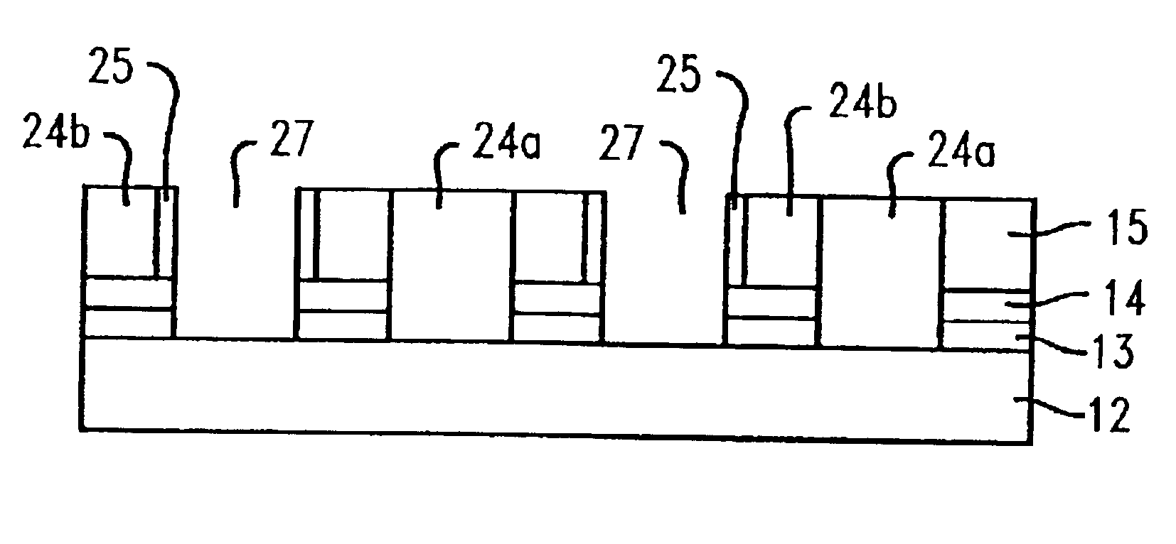
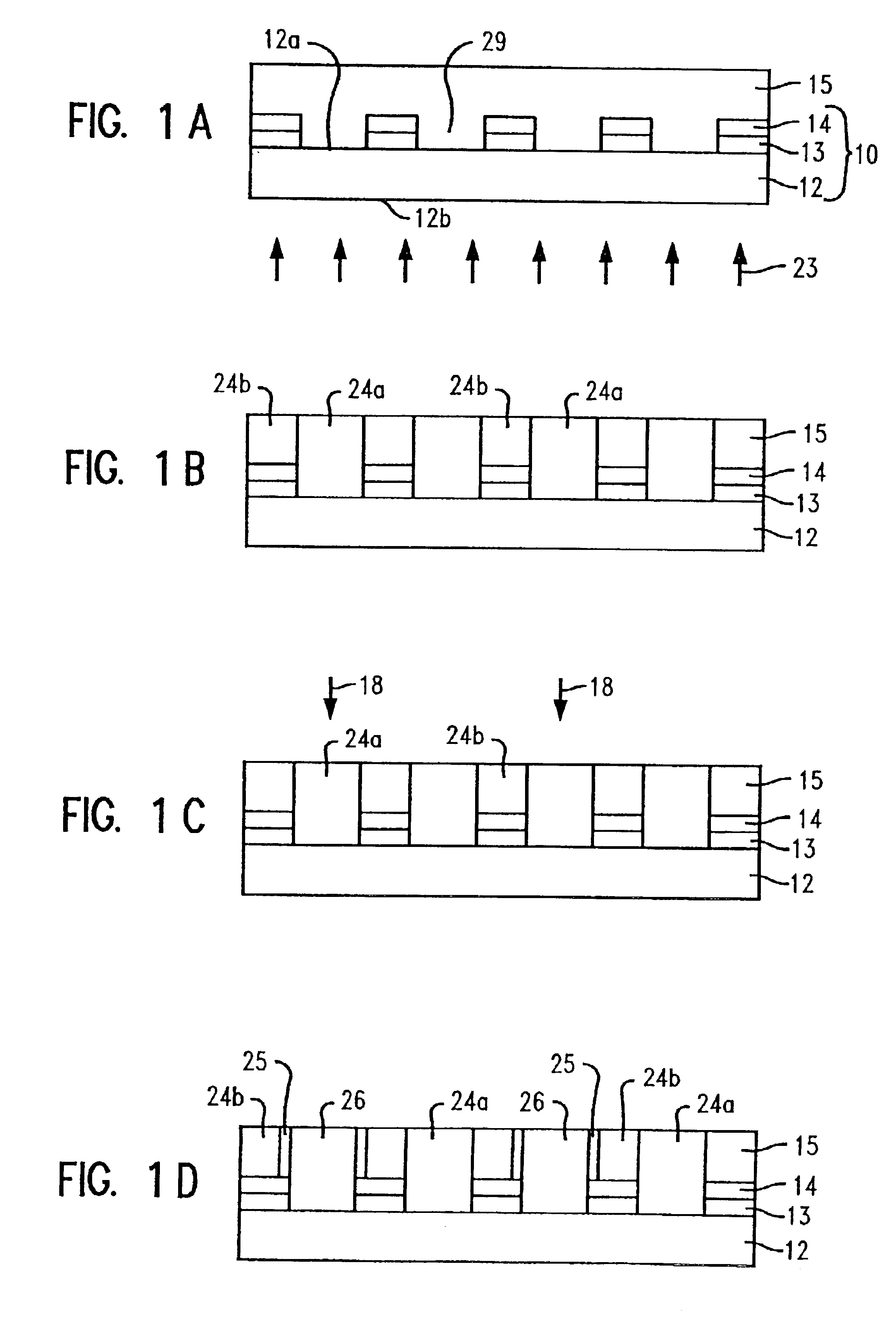
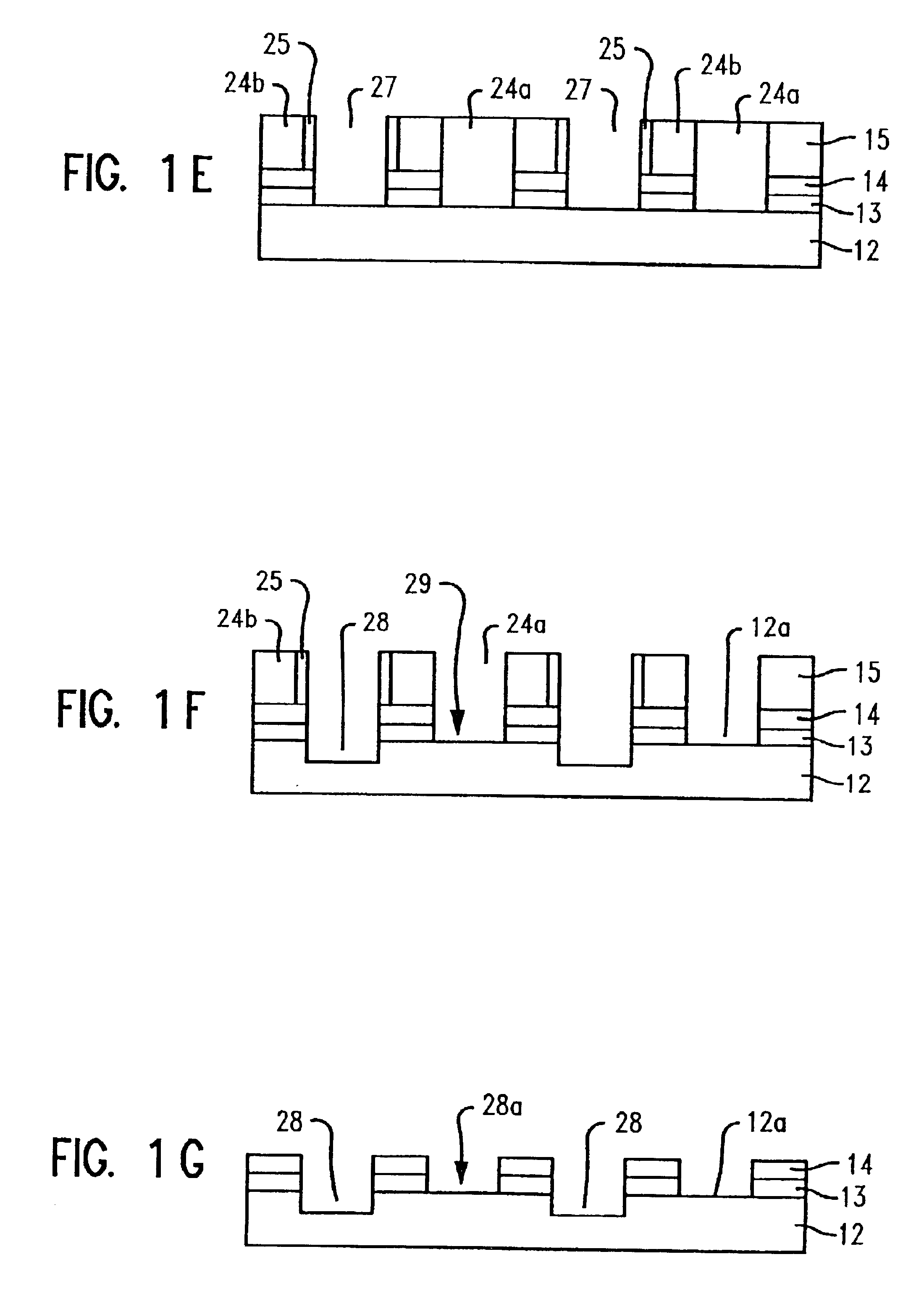
In describing the preferred embodiments of the present invention, reference will be made herein to FIGS. 1A-3 of the drawings in which like numerals refer to like features of the invention. Features of the invention are not necessarily shown to scale in the drawings.

The present invention is directed to making phase shift masks, and, in particular, to making alternating phase shift masks, which masks contain an anti-reflective coating on the opaque design layer of the mask. The invention minimizes and / or avoids etching of the anti-reflective coating during the mask making method. For convenience, the following description will be directed to chrome-plated quartz or glass substrate photomasks which, as noted above, typically comprise a metal pattern such as chromium in a thickness of about 1000 .ANG. deposited on a transparent base such as glass or quartz.

The substrate of the mask is made from any material that will transmit electromagnetic radiation or other suitable actinic energy ...


PUM

PropertyMeasurementUnit
thicknessaaaaaaaaaa
optical wavelengthsaaaaaaaaaa

Abstract

A method and apparatus for making phase shift masks are provided wherein an anti-reflective coating used on an opaque pattern layer of the mask fully covers the opaque pattern layer and has not been etched in the etching process to form the phase shift mask. A two-exposure method to form the phase shift mask is used wherein a photoresist having a defined dose-to-clear level is coated on the surface of the mask and the lower surface of the mask is exposed to a blanket exposure in an energy amount less than the dose-to-clear level. The open areas of the upper surface of the mask to be etched are exposed to an energy dose in an amount less than the dose-to-clear level, with the sum of the amounts of the lower surface energy and upper surface energy being at least the dose-to-clear level. The method and apparatus minimizes and / or avoids etching of the anti-reflective coating.

Description

1. Field of the InventionThis invention relates to a method and apparatus for making phase shift masks used in the manufacture of semiconductor microcircuits and other electronic components to transfer a circuit pattern onto a workpiece, and, in particular, to a self-aligned alternating phase shift mask wherein etching of an anti-reflective coating used on the opaque patterns of the mask is avoided.2. Description of Related ArtIn the manufacture of circuit patterns on electronic components such as the manufacture of integrated circuits on semiconductor substrates photomasks are used to transfer the desired circuit pattern onto the substrate workpiece. Typically, a photomask comprises a patterned metal film such as chromium, nickel or aluminum in a thickness of about 1,000 .ANG. deposited on a transparent base such as glass or quartz. The photomask is generally manufactured by depositing a thin film of the metal on the surface of the transparent substrate, coating an anti-reflective ...

Claims


Application Information

Patent Timeline
Patent Type & Authority Patents(United States)
IPC IPC(8): G03F7/20G03F1/00G03F7/00G03F1/30
CPCG03F1/30G03F7/2022G03F7/0035
Inventor BUKOFSKY, SCOTT J.FONSECA, CARLOS A.HIBBS, MICHAEL S.LIEBMANN, LARS W.
Owner GLOBALFOUNDRIES US INC
Learn More