
Metal product containing ceramic dispersoids form in-situ

a technology of ceramic dispersoids and metal products, which is applied in the field of metal products containing ceramic dispersoids form in-situ, can solve the problems of inability to use dispersoids for recrystallation control, dispersion strengthening, and inability to form clusters,

Inactive Publication Date: 2004-04-20
ARCONIC INC
View PDF9 Cites 4 Cited by
  • Summary
  • Abstract
  • Description
  • Claims
  • Application Information

AI Technical Summary

Benefits of technology

Accordingly, it is an object of the present invention to provide a method for increasing the number densities of dispersoids in the liquid state and which then remain stable and dispersed in the solid state in metal alloys.
It is a further object of the present invention to produce uniformity in the dispersion of finely sized ceramic phase particles in metal and in alloys.
It is another object of the present invention to produce uniformly distributed, finely sized ceramic phase particles dispersed in-situ in a metal alloy in a process providing reaction times shorter than conventional approaches.

Problems solved by technology

Although conventional ceramic phase formation processes in metal offer some possibilities for the production of a wide range of reinforcement particle types and improved compatibility between the reinforcement and the matrix, the in-situ formed ceramic particles in metal are too large, e.g., on the order of several microns, and tend to form clusters.
In-situ formed ceramic particles having these sizes, i.e., of several microns, are candidates for use as reinforcement in a composite, but are not suitable for use as dispersoids for recrystallation control, for dispersion strengthening, or for use as a component for structure refinement.

Method used


Image

  • Metal product containing ceramic dispersoids form in-situ
  • Metal product containing ceramic dispersoids form in-situ
  • Metal product containing ceramic dispersoids form in-situ

Examples


example 2

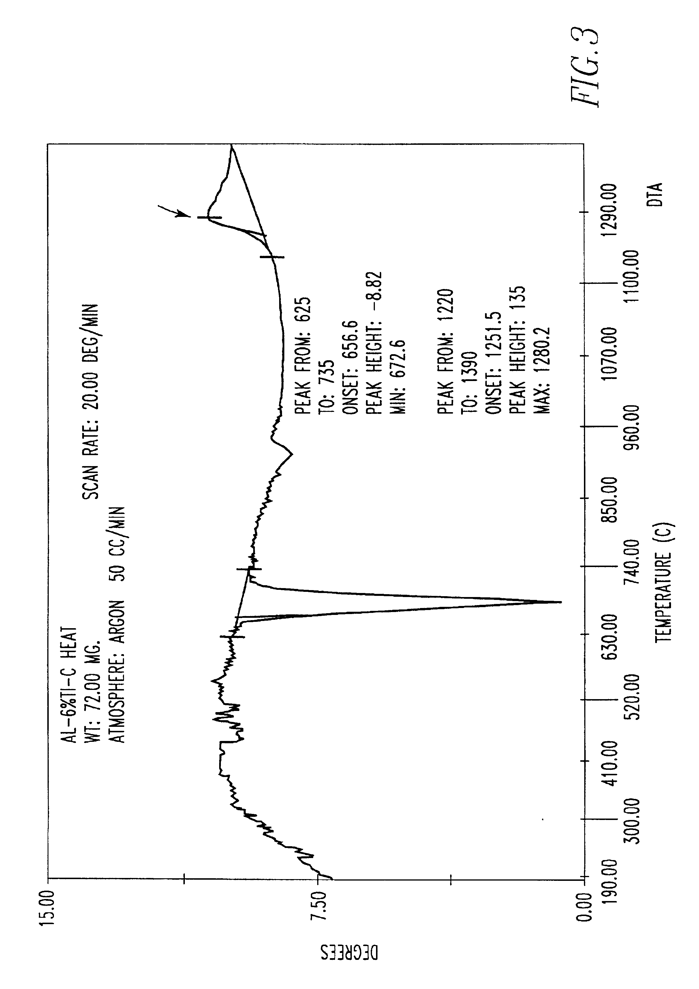
A mixture of 2.6 grams of Al-6% Ti powder and 0.32 grams graphite powder. 0.72 grams was formed and then placed in an Al.sub.2 O.sub.3 crucible of a DTA unit (Differential Thermal Analyzer). The crucible and sample was then heated to a temperature from room temperature 1300.degree. C. at a rate of 50.degree. C. / min under an argon atmosphere.

The results of the DTA is shown in FIG. 3. A peak shown at approximately 1275.degree. C. (as indicated by an arrow in FIG. 3) is an exothermic reaction, indicating the formation of TiC particles.

example 3

The procedure of Example 2 was repeated except that 2.6 grams of Al-5.7% Zr powder was mixed with 0.32 grams graphite powder. 0.71 grams. As before the mixture placed into an Al.sub.2 O.sub.3 crucible of a DTA unit and heated to a temperature. 1300.degree. C. at a rate of 50.degree. C. / min under an argon atmosphere.

The results of the DTA is shown in FIG. 4. A peak shown at approximately 1275.degree. C. (as indicated by an arrow in FIG. 4) is an exothermic reaction, indicating the formation of ZrC particles. These ZrC particles act as a dispersoid in aluminum alloys.

example 4

The procedure of Example 2 was repeated except that 2.6 grams of Al-5.1% V powder was mixed with 0.32 grams graphite powder. 0.71 grams of this mixture was then placed in an Al.sub.2 O.sub.3 crucible of a DTA unit. The sample was heated to a temperature 1300.degree. C. at a rate of 50.degree. C. / min under an argon atmosphere.

The results of the DTA is shown in FIG. 5. A peak shown at approximately 1270.degree. C. (as indicated by an arrow in FIG. 5) is an exothermic reaction, indicating the formation of VC particles. These VC particles act as a dispersoid in aluminum alloys.


PUM

PropertyMeasurementUnit
Particle sizeaaaaaaaaaa

Abstract

A novel method for producing a ceramic phase particle dispersoid in metal and a novel product composed thereof. The method includes (a) providing a molten composition consisting essentially of molten aluminum alloy containing molten metal selected form the group consisting of Zr, V and combinations thereof; (b) providing a chloride salt containing fine carbon particles; and (c) reacting the chloride salt containing fine carbon particles in the molten aluminum metal liquid with the molten metal liquid to form a uniform distribution of finely sized carbide particles formed and dispersed in-situ in an aluminum alloy matrix.

Description

The present invention relates to fine ceramic particles formed in-situ in metal and in alloys by the liquid-state process, and to products containing the fine ceramic particles formed in-situ in metal and in alloys by the liquid-state process. In one aspect, the present invention relates to a process for producing a material containing uniformly dispersed, finely sized ceramic phase particles, e.g., such as titanium carbide particles, formed in-situ in metals and in alloys by the liquid-state process.The aluminum and aerospace industries have long sought a method to ran control recrystallization of aluminum alloys during deformation operations to permit the design of aluminum airframes with improved structural properties.The metals industry today conventionally uses dispersoids, i.e., fine particles dispersed in the metal alloy, to control recrystallization and to increase dispersion strengthening at elevated temperatures. Such dispersoids of fine particles dispersed in the metal al...

Claims


Application Information

Patent Timeline
IPC IPC(8): C22C32/00C22C1/10C22B21/06C22B21/00
CPCC22B21/062C22C1/1036C22C32/0052
Inventor CHU, MEN GLENNRAY, SIBA P.
Owner ARCONIC INC
Learn More