
Method of forming spherical electrode surface for high intensity discharge lamp

a technology of high intensity discharge and electrode surface, which is applied in the manufacture of electric discharge tubes/lamps, non-electron-emitting shielding screens, and tube/lamp factory adjustment. it can solve the problems of premature degradation of light flux, deformation of electrode tip, and difficulty in prolonging the life of lamps

Inactive Publication Date: 2004-03-16
PANASONIC CORP
View PDF21 Cites 11 Cited by
  • Summary
  • Abstract
  • Description
  • Claims
  • Application Information

AI Technical Summary

Benefits of technology

"The present invention relates to an electrode for a high pressure discharge lamp, a high pressure discharge lamp, and a method of manufacturing the electrode. The technical effect of the invention is to improve the life of high pressure discharge lamps by designing an electrode that can better withstand deformation and wear caused by the high temperature and pressure of the arc generated during operation. The electrode is made by a process that allows for the rapid transfer of heat from the electrode tip to the electrode rod, suppressing deformation and wear of the electrode tip. This results in a longer life for the lamp and better performance. The electrode design also promotes the evaporation of light emitting material enclosed in the light-emitting tube. The invention is based on the development of an electrode design by a Japanese patent application and the manufacturing method described in Japanese Patent Laid-Open No. H9-16564."

Problems solved by technology

Namely, generally in high pressure discharge lamps of the short arc type, the tungsten which forms the electrode melts and disperses, the electrode tip becomes deformed and wears due to the temperature of the electrode end increasing excessively, while the dispersed tungsten is deposited on the inner surface of the light-emitting tube, causing blackening.
This blackening of the inner surface of the light-emitting tube causes premature degradation of light flux.
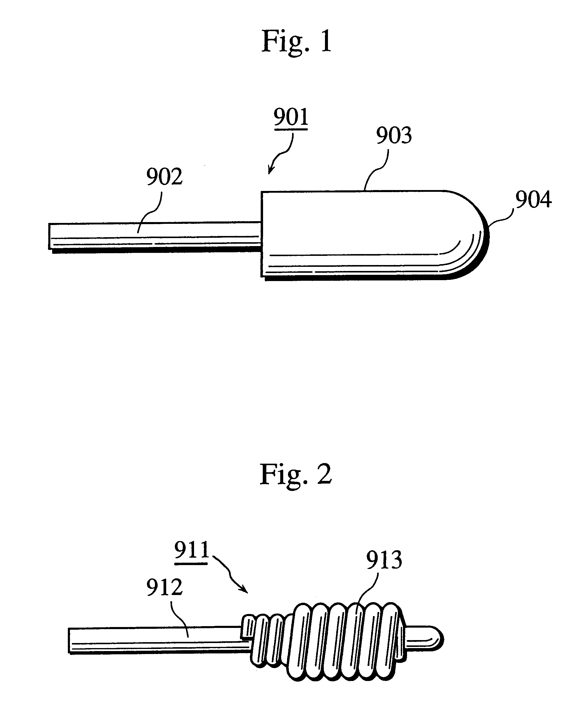
However, in a high pressure discharge lamp of the short arc type which uses an electrode such as the electrode 911, the above-described deformation and wear of the electrode tip due to melting and dispersion of the tungsten electrode material cannot be avoided, making lengthening the life of the lamp difficult.
However, as it is costly to manufacture electrodes by a grinding process, an electrode that can be manufactured cheaply while having the same basic construction as the electrode 901 in FIG. 1 was investigated.
However, when the inventors measured characteristics of mass produced lamps which use such electrodes, they discovered much variation between lamps in characteristics such as voltage and life, meaning such lamps lack commercial viability.
Deformities in the electrode can be suppressed due to the heat capacity increasing in the electrode tip of this kind of electrode whose average grain diameter in crystallization is large, contributing to lengthening the life of the high pressure discharge lamp.

Method used


Image

  • Method of forming spherical electrode surface for high intensity discharge lamp
  • Method of forming spherical electrode surface for high intensity discharge lamp
  • Method of forming spherical electrode surface for high intensity discharge lamp

Examples


first embodiment

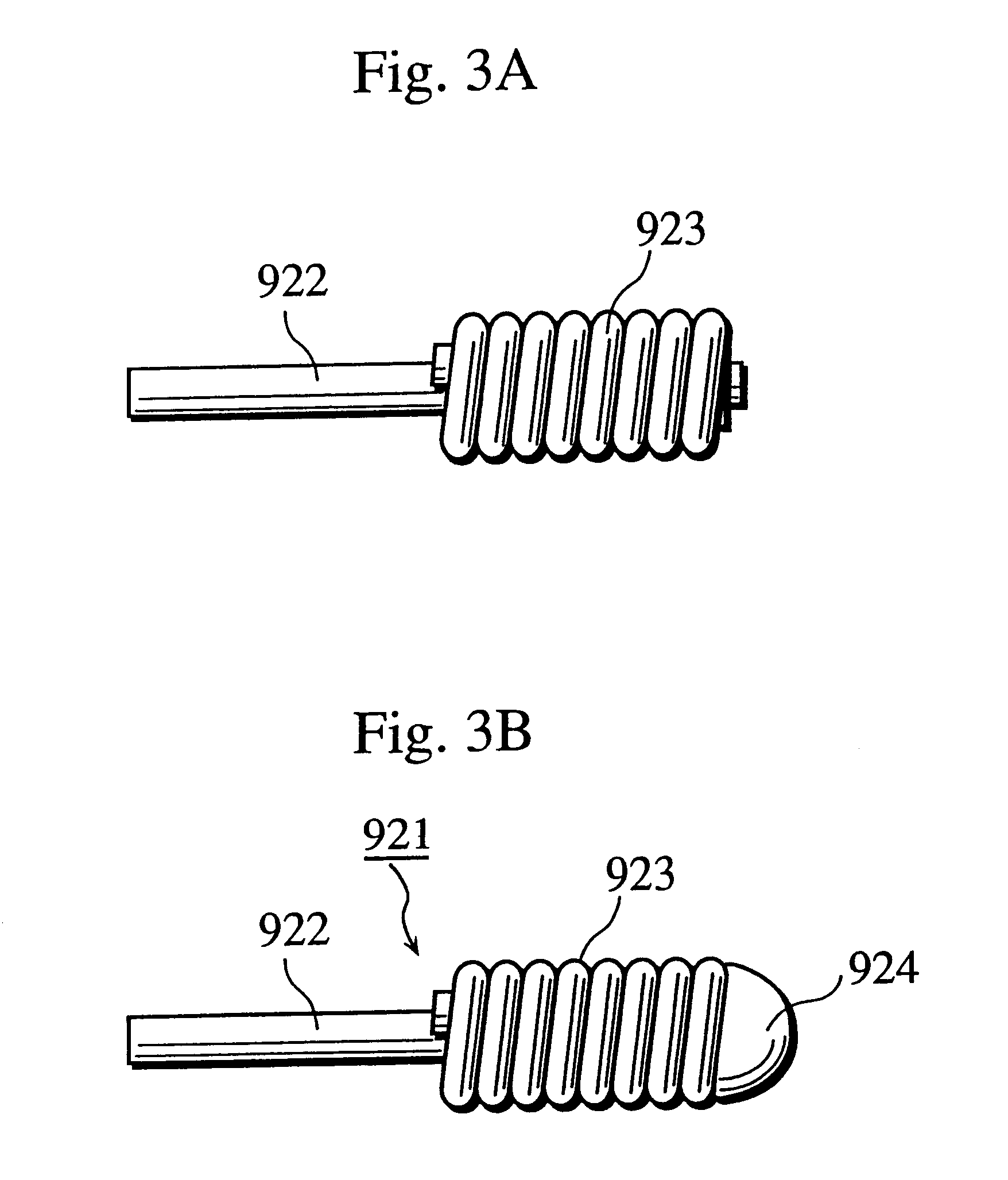
FIG. 4 shows the construction of a high pressure mercury lamp of the present embodiment of the present invention. As shown in FIG. 4, the high pressure mercury lamp of the present embodiment is provided with a light-emitting tube 101 with a discharge space 111 therein, two electrodes 102 and 103 placed so as to be in opposition with a predetermined distance (De) between the two electrodes, each electrode extending respectively from sealers 104 and 105 which are at either end of the discharge space 111. The electrodes 102 and 103 have the same basic structure as the electrode 921 shown in FIG. 3B, but the electrodes are manufactured according to the manufacturing method of the present invention, which will be explained later.

An enveloping vessel of the light-emitting tube 101 is formed from quartz and has a substantially spheroid shape. The opposing tungsten electrodes 102 and 103 are respectively hermetically sealed in the sealers 104 and 105 through molybdenum foils 106 and 107 res...

second embodiment

Next a second embodiment of the present invention will be explained.

As explained in the first embodiment, it is possible to suppress variations in the shape of the electrode tip by performing an intermittent heating fusing even by discharge arc fusion, but the inventors, estimated that a laser processing method would be superior in principle after further analyzing an electrode manufacturing method having a higher degree of accuracy than the method of the first embodiment. Namely, it was estimated that variations in fused shapes and dimensions could be reduced because a laser beam used in a laser processing method can irradiate on the electrode tip 124 controlling irradiation position and output more accurately.

Thus the inventors performed an investigation of an electrode manufacturing method according to a laser processing method. Lasers such as CO.sub.2 lasers, and laser diodes (LD, semiconductor lasers) are appropriate for use in metal processing, but the inventors chose to use a...


PUM

PropertyMeasurementUnit
repeat frequencyaaaaaaaaaa
distanceaaaaaaaaaa
lengthaaaaaaaaaa

Abstract

A high pressure discharge lamp which achieves a long life of at least 3000 hours and in which variations in lamp characteristics are suppressed is disclosed. In the high pressure discharge lamp of the present invention, during manufacturing of an electrode, a covering member 123 having a coil shape and being made of refractory metal is applied on a discharge side end of an electrode rod 122 made of refractory metal so as to cover a circumference of the electrode rod 122 in a vicinity of the discharge side end. The discharge side end 124 on which the covering member 123 is applied is fused into a semi-sphere by intermittently heat fusing the discharge side end according, for instance, to arc discharge or laser irradiation.

Description

This application is based on Japanese Patent Application No. 2000-116699, No. 2000-188785, and No. 2001-94226 with domestic priority claimed from the former two applications, the content of which are hereby incorporated by reference.(1) Field of the InventionThe present invention relates to an electrode for a high pressure discharge lamp, a high pressure discharge lamp, and a method of manufacturing therefor.(2) Description of Related ArtIn recent years there has been active development of projection type image display apparatuses such as liquid crystal projectors. In such a projection type image display apparatus it is necessary to have a high intensity light source close to a point light source. Generally a high pressure discharge lamp such as a high pressure mercury lamp or a metal halide lamp of the short arc type is used as this kind of light source.One of the main technical tasks when developing high pressure discharge lamps of the short arc type is lengthening the life by imp...

Claims


Application Information

Patent Timeline
Patent Type & Authority Patents(United States)
IPC IPC(8): H01J61/06H01J61/073
CPCH01J61/073H01J61/822H01J61/86
Inventor TSUTATANI, TAKASHIKITAHARA, YOSHIKISHIMIZU, TOSHIYUKI
Owner PANASONIC CORP
Learn More