
Carbon foam, graphite foam and production processes of these

a technology of graphite foam and carbon foam, which is applied in the field of carbon foam, graphite foam and production processes of, can solve the problems of poor oxidation resistance at high temperatures, poor corrosion resistance in chemical reactions, and insufficient thermal conductivity of conventional foam made of thermoplastic resin

Inactive Publication Date: 2004-02-10
MITSUBISHI GAS CHEM CO INC
View PDF3 Cites 36 Cited by
  • Summary
  • Abstract
  • Description
  • Claims
  • Application Information

AI Technical Summary

Benefits of technology

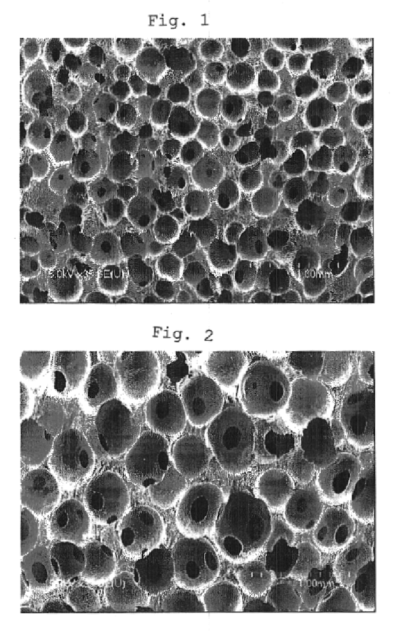
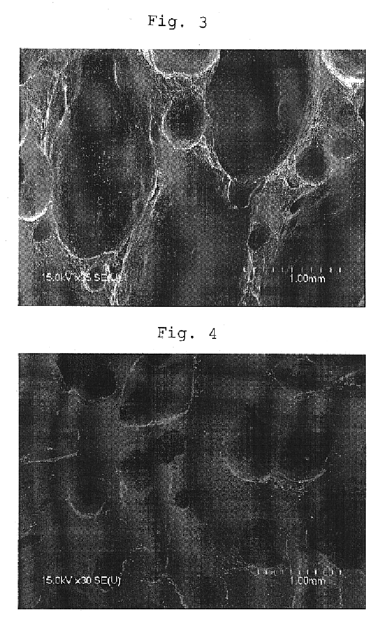
As described in detail above, owing to the use of the raw material pitch based on the present invention 1, there can be industrially stably produced a carbon foam having a uniform open cell structure. Further, owing to the use of the raw material pitch based on the present invention 2, there can be produced a carbon foam having a uniform open cell structure at such a pressure of 5 MPa or less, preferably 4 MPa or less, more preferably 3 MPa or less, that an operation can be industrially stably performed. Further, a graphite foam having a uniform open cell structure together with a high graphitization degree can be industrially stably produced by graphitizing the above carbon foam at 2,000.degree. C. or higher.

Problems solved by technology

However, a conventional foam made of a thermoplastic resin can not be used.
Since, however, thermosetting resin-based foams form a hard-to-graphitize carbon, the thermosetting resin-based foams are poor in oxidation resistance at high temperatures or corrosion resistance in a chemical reaction and are insufficient in thermal conductivity.
Further, foams made of a ceramic are excellent in oxidation resistance but are very poor in thermal conductivity and electrical conductivity.
However, since the nature of a raw material pitch required for industrially stably producing a foam of which the shape and size of a cell are uniformly controlled and which has excellent properties such as chemical stability, heat resistance and oxidation resistance, is unknown, a pitch designed as a raw material for a foam has been not yet provided.
Therefore, it is difficult to control the physical properties of a foam.
Further, nonuniform parts exist in large quantities in a generated foam during the production of a foam so that the problem is that the yield of a product decreases as a result.
That is, it is difficult to industrially stably produce a foam which has a uniform cell structure and various properties not hitherto attained, such as heat resistance, thermal conductivity, chemical stability, electrical conductivity, strength and diffusivity, from a generally-used conventional pitch with the physical properties of the foam having the above properties being controlled.
Therefore, it is difficult to produce a foam industrially economically.
When the pitch has a very high softening point of more than 300.degree. C., the fluidity of the pitch during melting is poor in a foam-producing step to be described later.
In this case, therefore, it is difficult to convert the pitch into a uniform block having no bubbles in a die before the formation of a foam so that voids which are a cause of a decrease in strength are apt to occur inside a foam as a product, which is not preferred industrially.
On the other hand, when the pitch has an aromatic carbon index fa value of less than 0.80, industrially undesirably, a fine cell structure is not formed either and at the same time the carbonization yield is small.
Since the raw material of a known conventional mesophase pitch of petroleum type or coal type is a byproduct, the precise control of physical properties of a mesophase pitch, which precise control is to be done in the present invention, is difficult and the above known conventional mesophase pitch is poor in the stability of nature and has a lot of impurities such as metal contents.

Method used


Image

  • Carbon foam, graphite foam and production processes of these
  • Carbon foam, graphite foam and production processes of these

Examples


example 1

Naphthalene was polymerized in the presence of a superacid catalyst HF-BF.sub.3 to obtain a raw material pitch (catalyst molar ratio: naphthalene / HF / BF.sub.3 =1 / 0.35 / 0.15, reaction temperature: 265.degree. C.). The softening point of the above pitch according to a flow tester was 227.degree. C. The atom ratio (H / C) of hydrogen to carbon was 0.606. The ratio (Daromatic / Daliphatic) of the absorption intensity of an aromatic C--H stretching vibration, measured with FT-IR, to the absorption intensity of an aliphatic C--H stretching vibration, measured with FT-IR, was 0.507. The aromatic carbon index fa value calculated by the formula (1) was 0.85. The optically anisotropic content of the pitch according to an observation with a polarization microscopy was 100%, and the pitch was a mesophase pitch.

2 g of the above mesophase pitch was placed in a cylindrical vessel which was made of aluminum and had an internal diameter of 13 mm, a depth of 29.15 mm and an internal volume of 4.17 cm.sup.3...

example 2

The same raw material pitch as that in Example 1 was used, and an investigation was carried out in the same manner as in Example 1 except that the pressure was increased to 3.5 MPa with nitrogen while keeping the temperature of 350.degree. C. and the temperature was increased up to 550.degree. C. at a rate of 2.degree. C. / minute. Tables 1 and 2 show the results.

examples 3 and 4

An investigation was carried out in the same manner as in Example 1 or Example 2 except that a raw material pitch was synthesized in a catalyst ratio of naphthalene / HF / BF.sub.3 =1 / 0.32 / 0.074 at a synthetic temperature of 245.degree. C. Table 1 shows the results.


PUM

PropertyMeasurementUnit
softening pointaaaaaaaaaa
pressureaaaaaaaaaa
temperatureaaaaaaaaaa

Abstract

A carbon foam obtained by heat-treating a mesophase pitch whose softening point is 300° C. or less according to an elevated flow tester, whose ratio (Daromatic / Daliphatic) of the absorption intensity of an aromatic C-H stretching vibration, measured with FT-IR, to the absorption intensity of an aliphatic C-H stretching vibration, measured with FT-IR, is 4.0 or less and whose optically anisotropic content is at least 80%, a graphite foam obtained by heat-treating the carbon foam recited above at a temperature of 2,000° C. or higher and production processes of these.

Description

The present invention relates to a carbonaceous or graphitic carbon material which is obtained from a mesophase pitch as a raw material and which is excellent in heat resistance and chemical stability and has a uniform open cell structure and production processes of theses.PRIOR ARTS OF THE INVENTIONVarious foam materials, such as a plastic foam, obtained from a resin as a raw material are widely applied to heat insulating materials, cushioning materials or the like. In recent years, it is thought to apply foam materials to fields requiring various properties not heretofore required such as heat resistance, thermal conductivity, chemical stability, electrical conductivity, strength, gas diffusivity, etc. For example, the above fields include a gas diffusion electrode of a fuel cell, a bipolar plate and the like. However, a conventional foam made of a thermoplastic resin can not be used. Accordingly, the use of a thermosetting resin foam, a carbon foam obtained by carbonizing a therm...

Claims


Application Information

Patent Timeline
Patent Type & Authority Patents(United States)
IPC IPC(8): C04B38/00
CPCC04B38/0022C04B35/524C04B38/0058C04B38/0067C04B38/0074C04B35/52C04B35/522
Inventor KANNO, KOICHITSURUYA, HIROTAKAFUJIURA, RYUJIKOSHIKAWA, TAKESHIWATANABE, FUMITAKA
Owner MITSUBISHI GAS CHEM CO INC
Learn More