Eureka AIR delivers breakthrough ideas for toughest innovation challenges, trusted by R&D personnel around the world.

Motor drive parameters

a motor drive and parameter technology, applied in the direction of motor/generator/converter stopper, motor/electric converter control, instruments, etc., can solve the problems of motor drive transistor switching loss much higher, mechanical stress, and ultimate so as to reduce mechanical failure of bonded wires, improve variable motor drive operation, and avoid excessive thermal stress

Inactive Publication Date: 2002-11-19
OTIS ELEVATOR CO
View PDF10 Cites 27 Cited by
  • Summary
  • Abstract
  • Description
  • Claims
  • Application Information

AI Technical Summary

Benefits of technology

Objects of the present invention include avoiding excessive thermal stress in solid state switches utilized in variable speed motor drives; avoiding excessive junction / heatsink (chassis) temperature differentials in such drives; predicting lifetime and failure modes of solid state switches in variable speed motor drives; utilizing variable speed motor drives maximally without creating excessive thermal stresses therein; reducing mechanical failure of bonded wires in such drives; improving variable motor drive operation; and providing variable speed motor drives that can automatically adjust operation to suit various loads and to suit different utilizations.
According still further to the invention, the slew rate (rate of change with time) of decreasing temperature, and therefore of increasing switching frequency, maximum load or diode duty cycle, is limited to prevent changes from following motor speed and / or load variations; the slew rate limit may be a function of motor speed; and upper and lower limits may be applied to switching frequency or maximum load and to diode duty cycle. Temperature information may be accumulated over time to predict device life, thereby to permit replacement only as realistically needed. The motor drive can thereby custom design its operating characteristics to suit any utilization to which it is put, e.g., one type of elevator or another type of elevator, as well as to alter its operation on a use-by-use basis so as to suit the duty imposed during each use of the motor, such as each run of an elevator.

Problems solved by technology

Particularly, thermal differences between the solid state junctions and the thermal sink create mechanical stress and ultimate failure of bonded wires.
It is known that transistor switching losses in motor drives are much higher than diode switching losses or conduction losses of either diodes or transistors.
However, such operation leaves selected diodes in a conducting state for long time segments, which must be accommodated in the design of the motor drive.
Although switching losses and therefore device temperatures can be reduced by using lower switching frequencies, such lower switching frequencies produce noise which is objectionable in certain environments, such as elevators.

Method used


Image

  • Motor drive parameters
  • Motor drive parameters
  • Motor drive parameters

Examples


Embodiment Construction

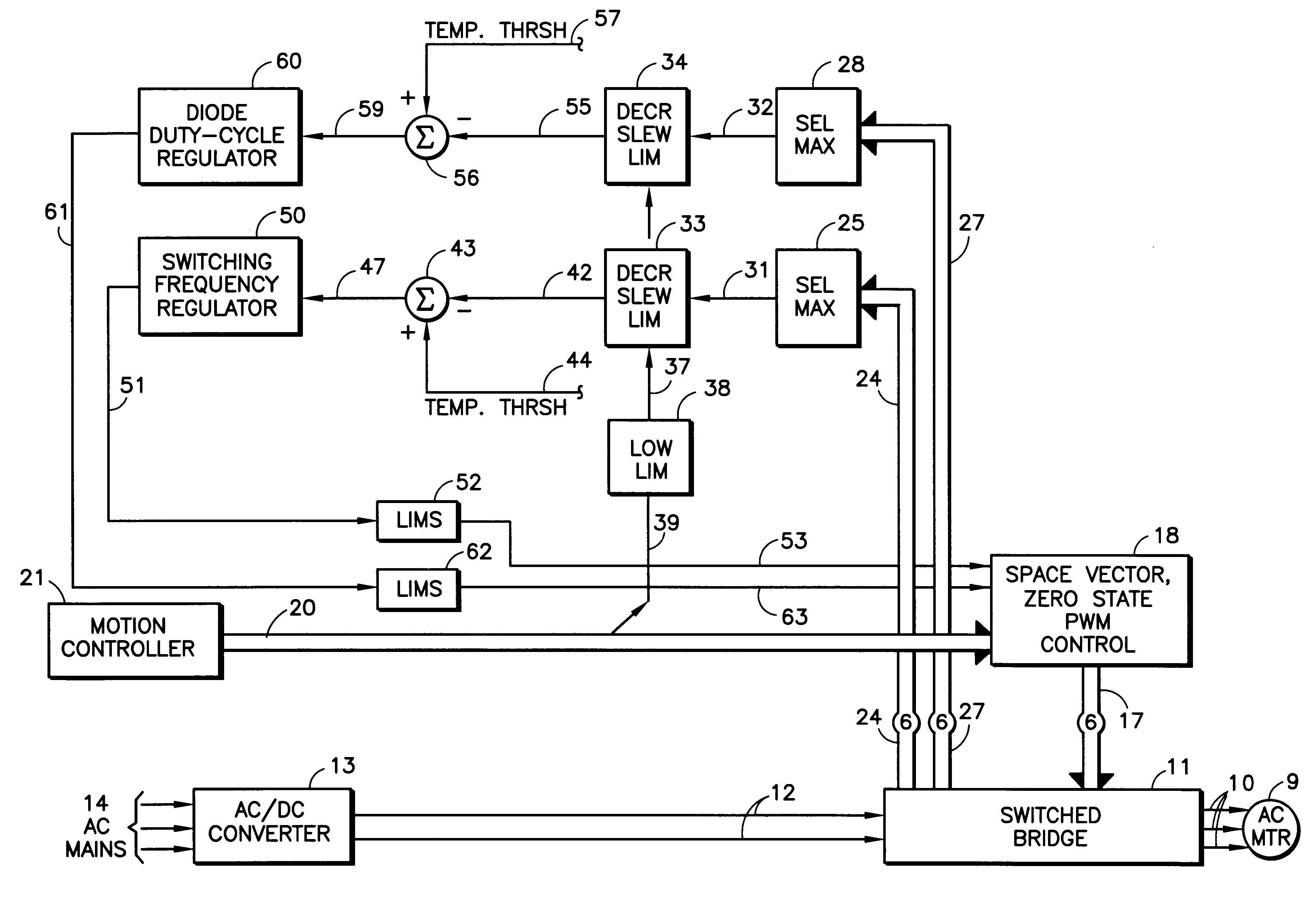
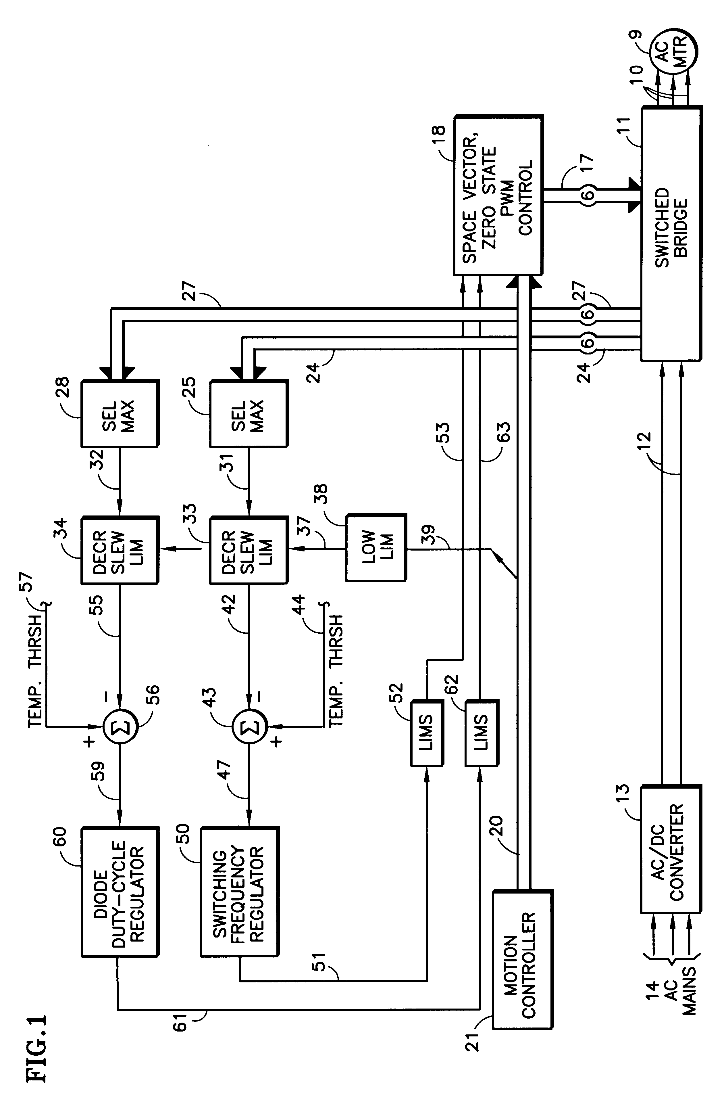
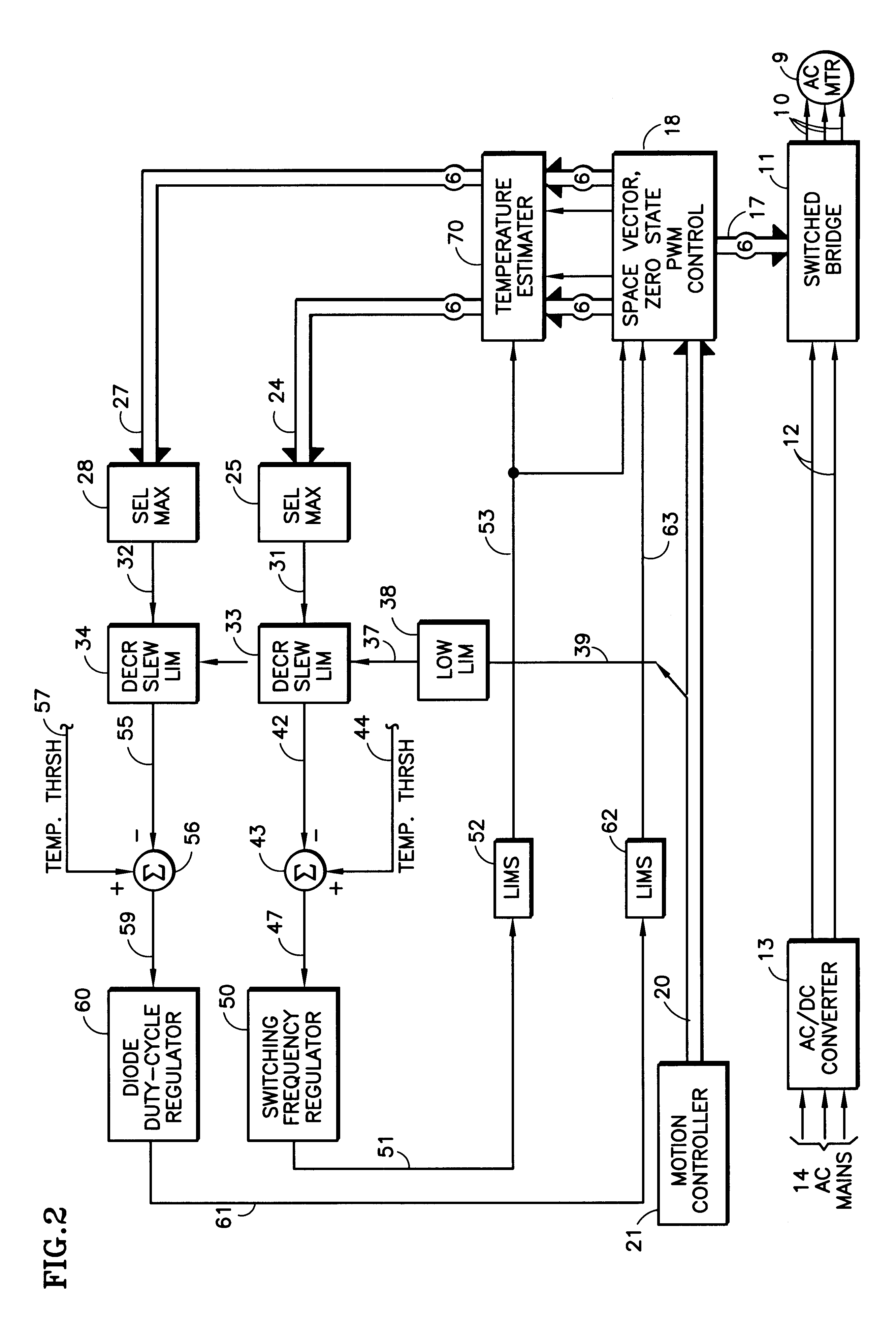
Referring to FIG. 1, an AC motor 9 (such as an induction motor or a permanent magnet motor) is provided power over lines 10 from a switch bridge 11 which in turn is provided DC power over lines 12 from an AC to DC converter 13, which is powered by AC mains 14. The switch bridge 11 may typically comprise a bridge having six insulated gate bipolar transistors (IGBTs), each with an anti-parallel diode, the operation of which is controlled by six individual switching signals on lines 17 from a space vector, zero state, pulse width modulation (PWM) control 18. The control 18 may be conventional or may take the form of that disclosed in the aforementioned applications. In the exemplary embodiments herein in which the motor 9 is part of an elevator drive, the PWM control 18 will respond to signals on a trunk of lines 20 from a motion controller 21 of any conventional type which determines when the elevator should stop, how it should accelerate and to what speed, and when it should slow dow...


PUM


Abstract

The temperature (25, 33, 43) of solid state switching devices in variable speed motor drives (11, 18), such as elevator motor drives, are utilized to reduce the load on the drive, by reducing the switching frequency (50) or the commanded load (110). The choice between the preferred non-switching zero state and an alternative zero state is determined (60) by temperature (28, 34, 56) of the switched transistor's anti-parallel diode. The rate of recognizing reduced temperatures is limited (33, 34) to avoid motor speed and / or load variations. The temperature may either be measured (24, 27) or determined (70) from models utilizing manufacturer product specification and normalized thermal transient response from the transistor / diode package to a heat sink.

Description

This invention relates to controlling the parameters of a variable speed motor drive in response to the temperature of the solid state switches within the drive.Solid state devices used in motor drives, typically insulated gate bipolar transistors (IGBTs) and their anti-parallel diodes, undergo thermal stress as a function of the load on the motor and the switching frequency in the drive. Particularly, thermal differences between the solid state junctions and the thermal sink create mechanical stress and ultimate failure of bonded wires. Exemplary motor drives are disclosed in U.S. patent applications Ser. No. 09 / 310,393 and Ser. No. 09 / 310,31 1. Since thermal stress of solid state devices results in failure thereof, drives are typically designed to carry more than the anticipated load so as to reduce the possibility and delay the onset of failure, by reducing thermal stresses which occur during the worst-case drive situations.The zero state of space vector, zero state, pulse width ...

Claims


Application Information

Patent Timeline
Patent Type & Authority Patents(United States)
IPC IPC(8): H02P27/04H02P29/02
CPCH02P27/042H02P29/02H02P27/048
Inventor THEBEAU, RONNIE E.MARVIN, DARYL J.CZERWINSKI, CHRISTOPHER S.GREINER, NEIL A.PIEDRA, EDWARD D.
Owner OTIS ELEVATOR CO
Why Eureka
Eureka Blog
Learn More