
Liquid processing method making use of pipette device and apparatus for same

a pipette and liquid processing technology, which is applied in the field of liquid processing methods using pipette devices and apparatus for same, can solve the problems of difficult to smoothly execute analysis, work for isolating dna from tissue or cell, and complex work, and achieves high precision

Inactive Publication Date: 2002-09-24
PRECISION SYST SCI
View PDF33 Cites 80 Cited by
  • Summary
  • Abstract
  • Description
  • Claims
  • Application Information

AI Technical Summary

Benefits of technology

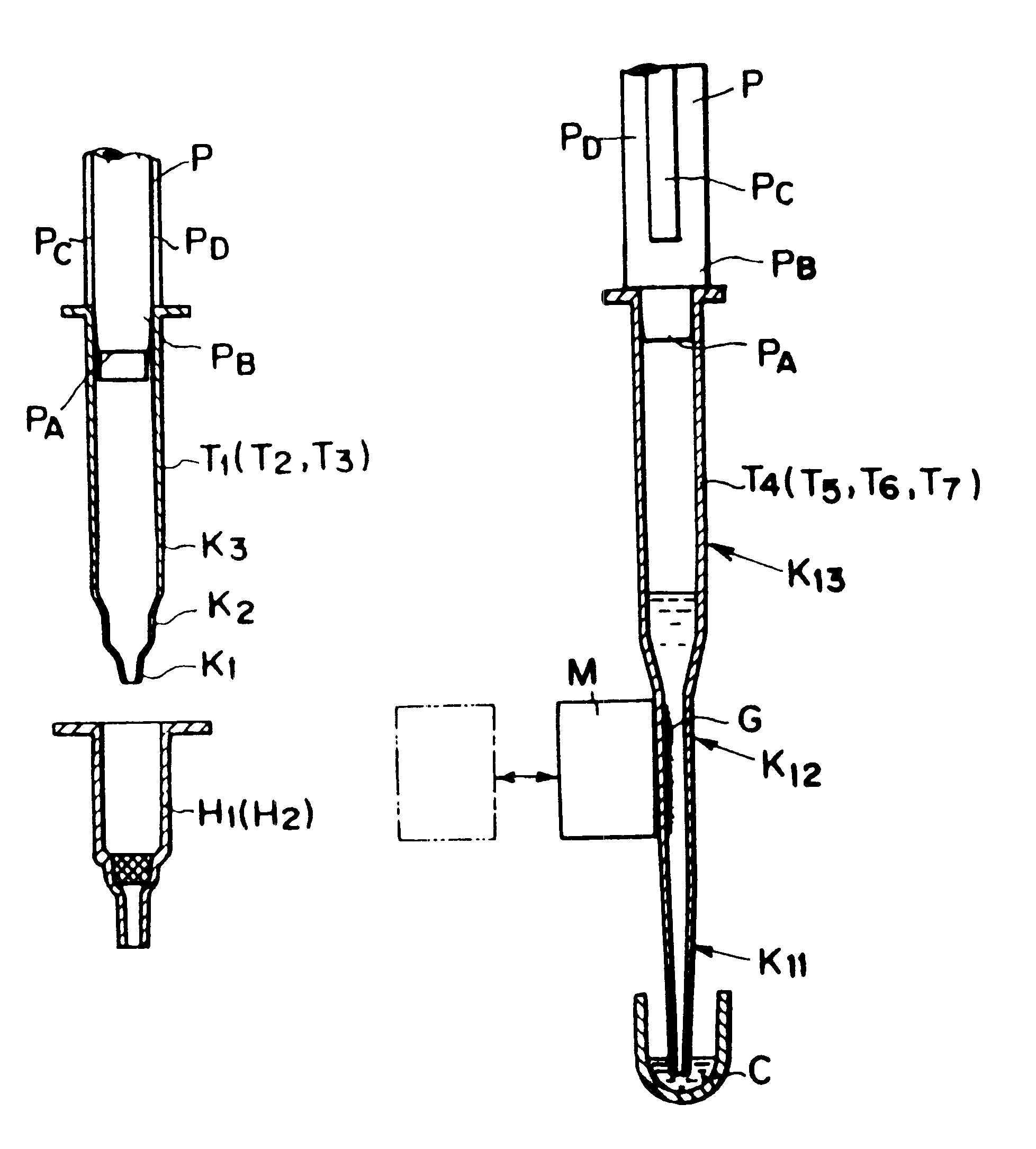
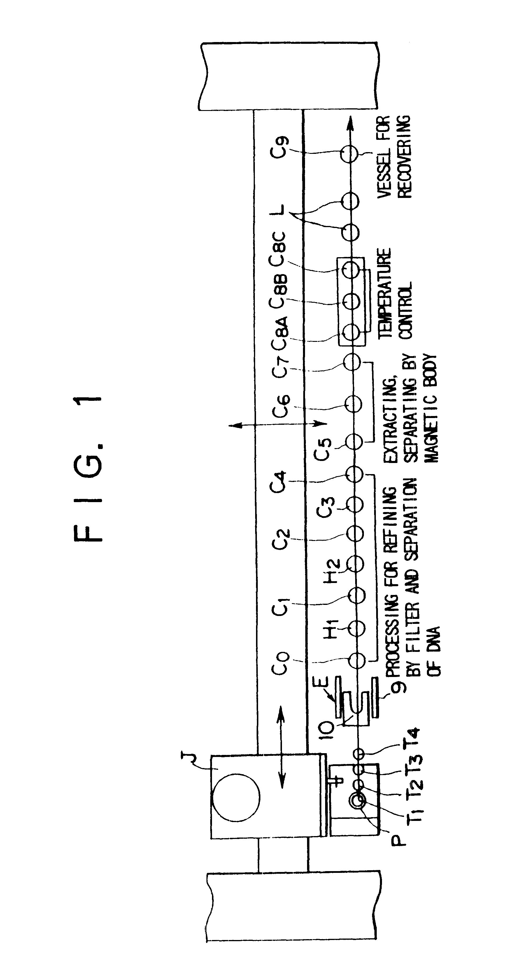
Technological basis of the present invention is a liquid processing method making use of a pipette device which sucks a liquid containing a target high molecular substance via a chip detachably set in a sucking port or a discharging port of a liquid sucking / discharging line from inside of a vessel and transfers the liquid or the target high molecular substance to a target next processing position, and the chip has the sucked target high molecular substance deposited on magnetic particles and / or separated with a filter set in the chip. Namely, it is possible to automatically execute with high precision the works of quantifying, separating, taking out, pipetting, clarifying, condensing, diluting a liquid or a target high molecular substance as well as works of extracting, recovering, and isolating the substance by controlling the pipette device's operations for sucking and discharging the liquid and magnetic particles with a magnetic body and / or by a combination of a magnetic body and a filter.
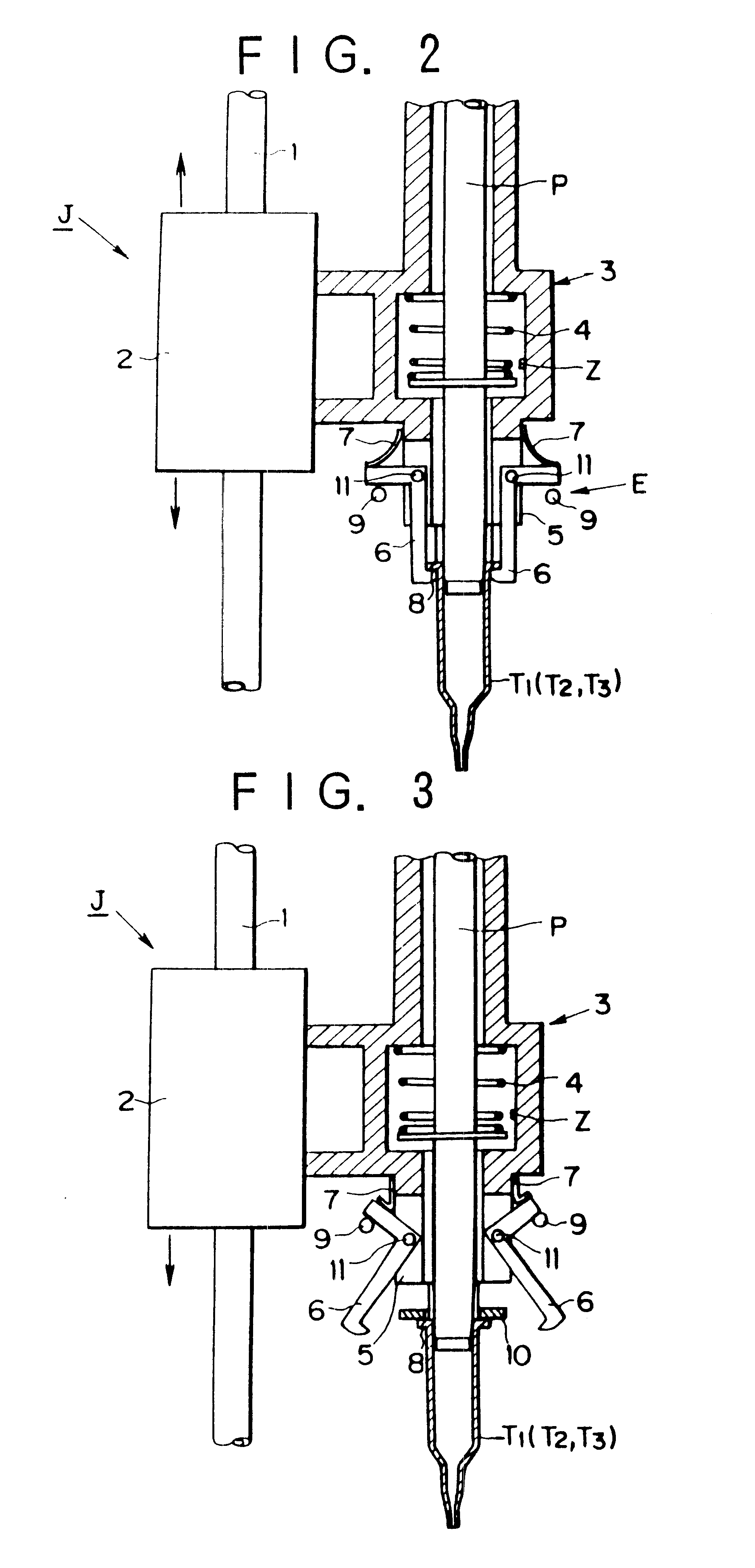
Furthermore in the present invention, the covering body comprises a flat surface section having a diameter larger than that of a bore of the thermostatic vessel and a maintenance groove section formed in a substantially central portion of the flat surface section and having the same bore as an external diameter of the liquid sucking / discharging line or the tip of the chip, and a bottom section of the maintenance groove section is formed with a thin film body which can be broken by the liquid sucking / discharging line or the chip, so that it is not necessary to separately provide a covering body supply means or a liquid sucking / discharging means, which largely simplifies this type of apparatus.

Problems solved by technology

However, in a case of man, for instance, a particular target gene DNA is one millionth or below of all genome DNA, and for this reason actually a quantity of DNA obtainable for testing is quite small, while a quantity of DNA and RNA not necessary for a particular experiment is quite large, which makes it difficult to execute analysis smoothly.
As described above, it is possible to extract, recover, and isolate DNA for structural analysis of a gene in, for instance, DNA diagnosis according to any of the known methods as described above, but a work for isolating DNA from the tissue or cells as described above is, as clearly understood from the sequence for extracting DNA from the tissue or cells as described above, extremely complicated, and a long period of time is required, which is disadvantageous.
Namely, in a case of centrifugation, automation of processes for loading and taking out vessels is very difficult, and also it is very difficult to mechanically separate supernatant from precipitates after centrifugation, and for this reason its applicability for various purpose is disadvantageously poor.
In a case of high speed liquid chromatography, a separation column is basically consumable, injection for a sample to the column or time management for separation can not be mechanized, and also different samples pass through the column, which disadvantageously makes it impossible to completely prevent contamination of the column.
Furthermore, in a case of gel electrophoresis, adjustment of gel can not be mechanized, and this method has generally been used as a basic technique for separation of DNA, but the separated pieces must be taken out manually, which is disadvantageous.
The dispo-column method is one of technic which can be embodied as a kit for separation of a particular DNA piece, but the cost is very expensive, and its applicability is narrow.
In addition, controls over pipetting and liquid passing through the column are difficult, and there are many problems in mechanization of this method.
In the dialysis method, a long period of time is required for dialysis, and also it is hard to apply this method when a quantity of sample is small, so that this method has not been used widely.
The glass powder method is an excellent method of extracting DNA making use of silicon dioxide, and the process is simple and convenient, but as the powder is separated with a filter or by way of centrifugation, it is difficult to automate the entire process.
Furthermore in a case of the magnetic particle cleaning nozzle method, the process can be automated by controlling the cylinder and attracting / discharging with magnetic particles, but basically it is impossible to prevent contamination only by cleaning the nozzle.

Method used


Image

  • Liquid processing method making use of pipette device and apparatus for same
  • Liquid processing method making use of pipette device and apparatus for same
  • Liquid processing method making use of pipette device and apparatus for same

Examples


first embodiment

The above description of the present invention assumes a case where the filter holders H.sub.1, H.sub.2, sample cell C.sub.0, and cells C.sub.1 to cell C.sub.9 are arrayed in the order of reaction steps, but the present invention is not limited to this configuration, and as shown in FIG. 20, excluding the sample cell C.sub.0 and DNA recovery cell C.sub.9, each of a group of cells C.sub.1 to C.sub.4 used for refining with a filter, a group of filter holders H.sub.1, H.sub.2, a group of cells C.sub.5 to C.sub.7 processed with the magnetic particles G, and a group of thermostatic cells C.sub.8A to C.sub.8C may be set in a cassette with the pipette nozzle P driven and controlled according to the processing sequence described above. It is needless to say that the covering body L may be provided in parallel to a cassette of the thermostatic cells C.sub.8A to C.sub.8C.

second embodiment

FIG. 21 shows the present invention, and this embodiment shows a case where a plurality of reaction lines, for instance, 4 arrays of reaction lines each having the same configuration as that of the single reaction line are provided and the lines are separated from each other with a partition wall X. It is needless to sat that, in this case, a required number of pipette nozzles are provided in series for each reaction line so that a plurality of samples can simultaneously be processed.

Also it should be noted that the reagent vessels Ra, Rb, Rc, Rd, Re, Rf arrayed along each of the reaction lines above and chips T.sub.5A, T.sub.5B, T.sub.5C, T.sub.5E, T.sub.5F each for pipetting each reagent are provided in parallel along the trajectories of the pipette nozzles P.sub.1, P.sub.2, P.sub.3, P.sub.4 moving along each of the reaction lines.

The partition wall X comprises a rectangular plate body having a size in a range including a tip section of each of the pipette nozzle P.sub.1, P.sub.2,...


PUM

PropertyMeasurementUnit
weightaaaaaaaaaa
pHaaaaaaaaaa
pHaaaaaaaaaa

Abstract

Technological preposition of the present invention is a liquid processing method making use of a pipette device which sucks a liquid containing a target high molecular substance from inside of a vessel through a chip detachably set on a sucking port or a discharging port of a liquid sucking / discharging line and transfers this liquid or target high molecular substance to the next target processing position for the purpose to execute such works as quantifying, separating, taking out, pipetting, clarifying condensing, and diluting a liquid or a target high molecular substance contained in a liquid and also such works as extracting, recovering, and isolating the target high molecular substance by means of sucking and discharging a liquid with a pipette device and controls by a magnetic body over magnetic particles and / or a filter combined according to the necessity, and the chip can isolate the target high molecular substance by having the substance attracted onto magnetic particles or with a filter set on each chip.

Description

The present invention relates to a liquid processing method making use of a pipette device and an apparatus for the same, with which works including for quantifying, separating, taking out, pipetting, clarifying, condensing, diluting a liquid or a target high molecular substances included in a liquid such as useful substances such as antibiotic substance, genetic substances such as DNA, and immunological substances such as antibodies, and / or works for extracting, recovering and isolating the target high molecular substance can automatically and accurately be executed by means of absorbing and discharging the liquid through a liquid absorbing / discharging line in the pipette device.In recent years, research activities for DNA or the like are very active in many fields including engineering, medical science, agriculture, physical science, pharmacology, and the purpose includes genome sequencing, clinical diagnosis, improvement of agricultural products, bacteriological inspection of foo...

Claims


Application Information

Patent Timeline
Patent Type & Authority Patents(United States)
IPC IPC(8): G01N35/00G01N35/10G01N33/50B01L3/02B01L7/00B01L99/00C12Q1/68G01N1/00G01N33/543G01N35/04
CPCB01L3/0275G01N35/0098G01N35/10G01N35/1065B01L3/0279B01L7/52B01L2300/0681B01L2300/087G01N35/1079G01N2035/0405G01N2035/103G01N2035/1053G01N2035/1055B03C1/01B03C1/0332B03C1/0335B03C1/288B03C2201/18B03C2201/26
Inventor TAJIMA, HIDEJI
Owner PRECISION SYST SCI
Learn More