In the thus assembled secondary battery, in the case of no capacity balance between the positive and the negative electrodes, there is a fear of causing various problems.
For example, in a case where the negative electrode has a less amount of active material and the
battery capacity of the negative electrode is smaller than that of the positive electrode, it is not possible to charge, into a space between carbon
layers of the negative electrode, all the
lithium ions
coming out from the positive electrode into the electrolyte at the charging reaction time, and the
lithium ions becomes excessive in the electrolyte, which forms
lithium metal therein and which may deposit a
dendrite (column-shape) on the negative electrode plate.
If such deposit grows, the separator interposed between both the electrode plates may be broken, which results in the short-circuit therebetween, and the performance of the battery may be extremely damaged.
However, as the
coating speed is increased, it becomes difficult to perform the mechanical control of the coater head so as to accord with the
coating speed, and it becomes impossible to exactly form the pattern in which the coated portions and the non-coated portions are alternately repeatedly formed.
Particularly, in a case where it is desired to form the non-coated portions, each having a relatively narrow area, intermittently repeatedly in the portion to be coated, it is extremely difficult to exactly form a pattern of the non-coated portion at a high speed.
Furthermore, for the reason that the motion of the coater head cannot follow the high
coating speed, local coating amount becomes slightly excessive at the respective supply-start positions, which results in the formation of a built-up (protruded) edge portion of the active material layer.
When the tailing phenomenon becomes remarkable, the
boundary line of the edge portion of the active material layer provides a wave-shape, thus being inconvenient.
Then, if the capacity balance between the positive electrode and the negative electrode is determined in the assumption of dispersion at the
peripheral edge portion of the active material for the positive electrode, much amount of the active material for the negative electrode is required, thus increasing material loss, and the
battery capacity is made small in
spite of the much using amount of the active material.
In the case where the edge portion of the active material layer is built up, a damage will be applied to the electrode plate and a pressing
machine at the press working time to the electrode, it will become difficult to finely wind up the electrode plate and, moreover, the separator will be likely broken in the battery, thus providing problems.
In the case of less patterning performance of the active material layer, there will be provided a problem that the automatic sensing of the positions of the active material layer and the non-coated portion is made difficult.
Accordingly, in a case where the first mentioned active material layer is formed with a worse patterning performance, a patterning performance of the active material layer formed to the latter mentioned surface will also become worse.
Furthermore, at the battery assembling time, the position of the non-coated position is automatically sensed, and in this time, in the case of worse patterning performance of the active material layer, this automatic sensing becomes itself difficult.
However, such reduction of the inconveniencies has a limit in its improvement, and moreover, it is difficult to increase the productivity of the electrode plates.
However, the methods not mechanically controlling the coater head are applicable to cases where a thin coating layer is formed, but not applicable to cases where a relatively thick layer such as active material layer is formed.
On the other hand, in the case of the latter mentioned method, that is, in the method in which the coated film is partially peeled by mechanical means such as knife after the formation of the coating film on the entire surface of the collector, the patterning performance is not made high and it is difficult to make smooth the edge portions of the active material layer, so that production of
powder at the edge portion is caused, thus providing problems.
When the
high polymer resin
layers are formed on both the surfaces of the collector and the collectors are overlapped, a blocking phenomenon is liable to be caused.
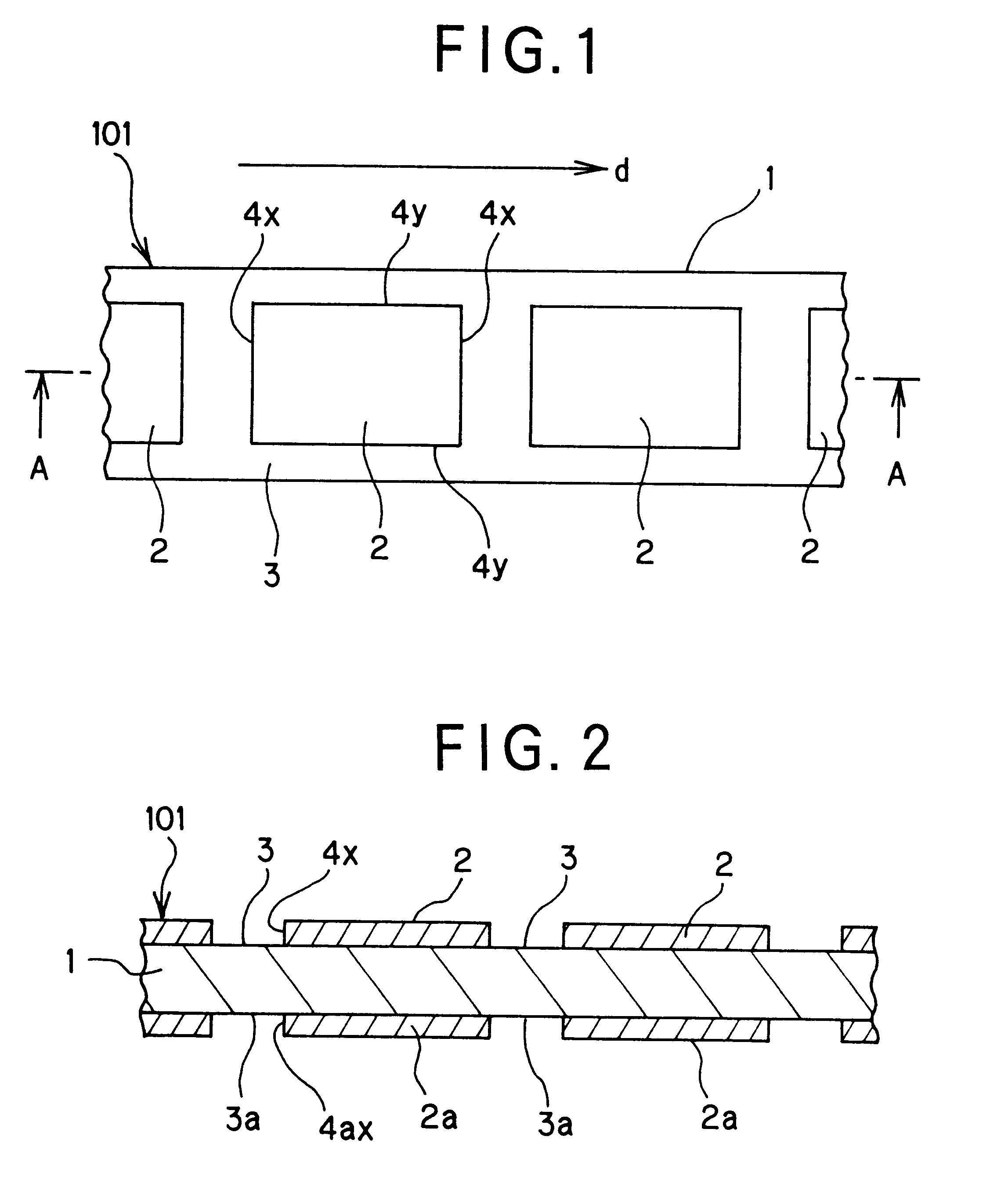
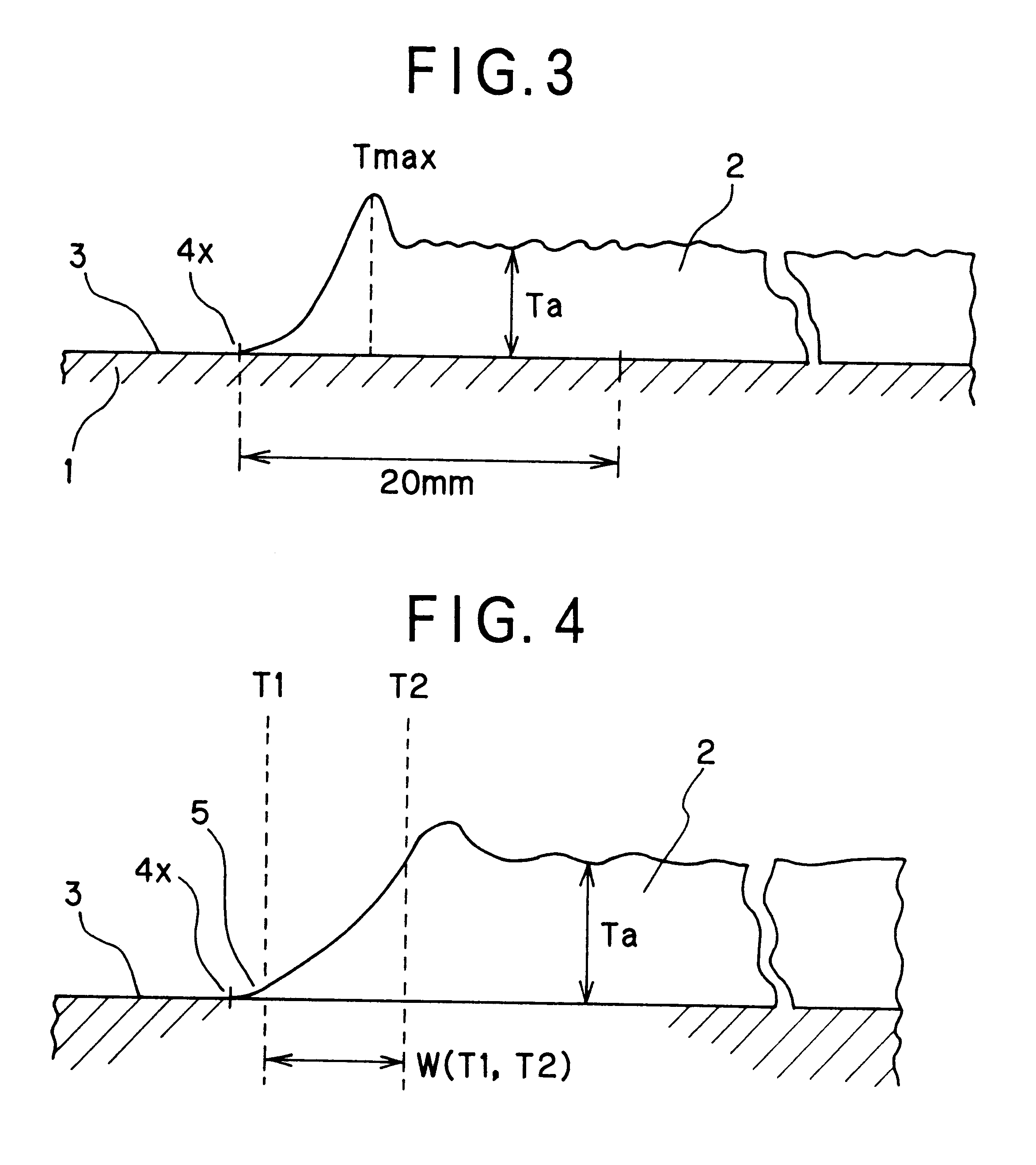
In this time, in a case where a horizontal resolving power at the thickness measuring time is too high, the magnitude of the thickness is made high because a particle shape on the surface of the active material layer 2 has been considered, and hence, the discrimination of the maximum thickness and the average thickness is made difficult.
In the case where the active material layer is formed by the conventional method in which a coater head is mechanically controlled, because the coating amount of the coating solution for the active material layer becomes locally excessive at the coating solution supply start position, a built-up portion is formed to the edge portion facing the arrangement direction of the active material layer, and hence, the condition of the Equation 1 mentioned above could not be satisfied.
Furthermore, in the case where the active material layer is formed by the conventional method in which a coater head is mechanically controlled, because the coating amount of the coating solution for the active material becomes locally short at the coating solution supply stop position, a long inclination is formed to the edge portion facing the arrangement direction of the active material layer, and hence, the condition of the Equation 2 mentioned above could not be satisfied.
Still furthermore, in the case where the active material layer is formed by the conventional method in which a coater head is mechanically controlled, because the tailing phenomenon of the active material layer is caused at the supply stop position of the coating solution for the active material layer, the edge portion facing the arrangement direction of the active material layer is waved, and hence, the conditions of the Equations 3 and 4 mentioned above could not be satisfied.
Further, the method which does not require the mechanical controlling of the coater head, for example, gravure coating method or gravure reverse coating method, it is possible to continuously form the desired pattern precisely at high speed, but these methods are limited in their use to the formation of relatively thin coating film.
In the case of less amount of the
high polymer resin, it becomes difficult to form the coating film, whereas in the case of less amount of the
powder, the blocking of the coated film will easily occur.
In the case of the pressing pressure of less than 500 kgf / cm.sup.2, it is difficult to obtain the uniformity of the active material layer, and in the case of the pressing pressure of more than 7500 kgf / cm.sup.2, there may cause a case where the electrode plate inclusive of the collector is damaged.
Since the
copper foil collector has a color near red color, the collector will not appear when a red coloring agent is used and there is a possibility of being difficult to be detected.
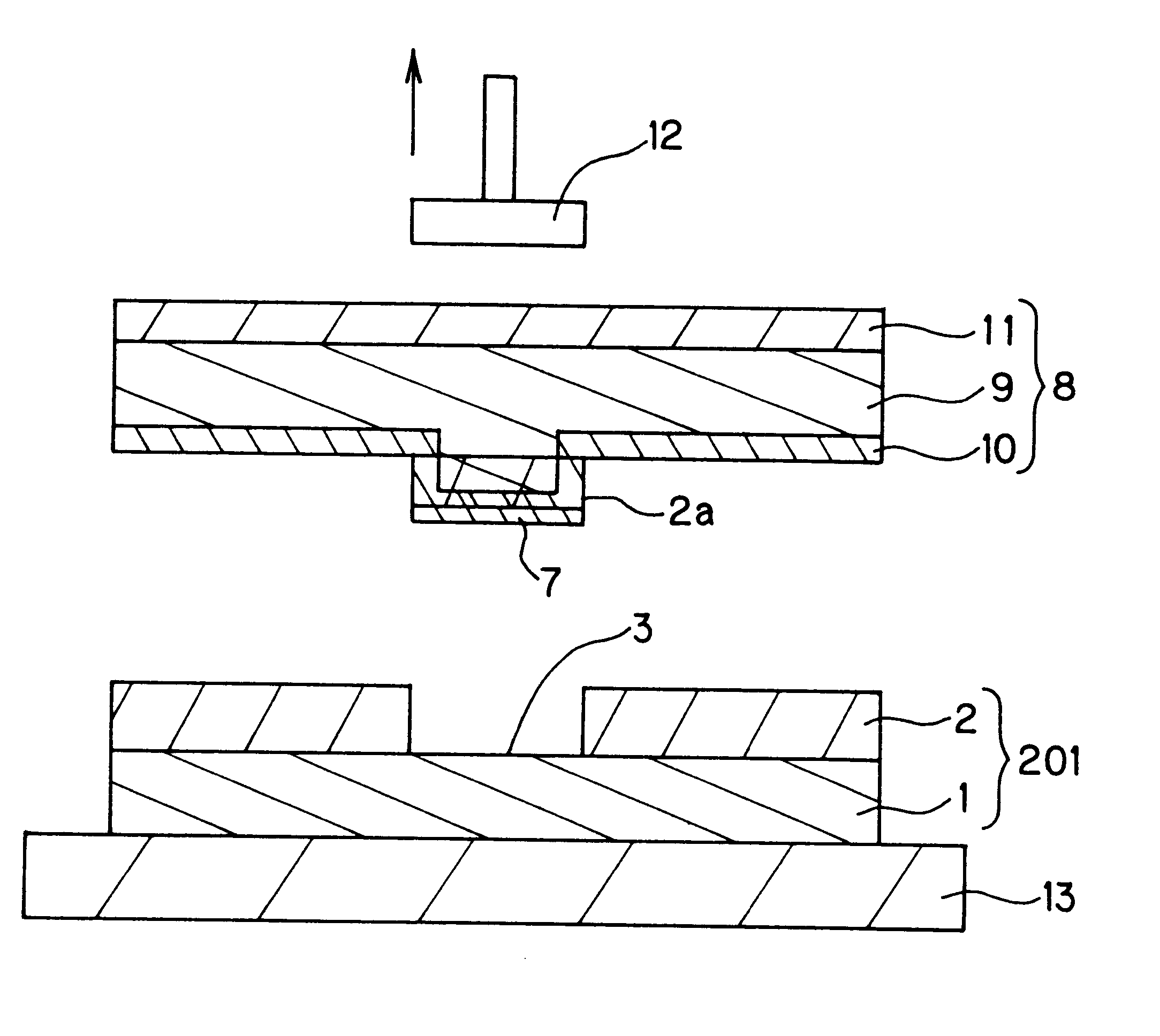
In the case of the
thermoplastic resin being too thin, it is difficult to sufficiently remove the active material layer 2s at the area forming the non-coated portion, and on the contrary, in the case of being too thick, it is difficult to form the active material layer 2s providing a pattern having a sharp shape.
In the case of high
low melting point, it is not economical in the viewpoint of energy and, moreover, there is a fear of damaging the collector 1 as the substrate at the time of being impregnated into the active material layer.
In the case of high
melt viscosity, it is not economical in the viewpoint of energy, and in the case of low
melt viscosity, the
wax is easily developed in the transverse direction at the time of being impregnated into the active material layer, thus being difficult to carry out the exact patterning.
In a case where the the
thermoplastic resin does not reach an adequately deep portion of the active material layer 2s, there may cause a case that the peeling has not been completed by one time of working.
