
Gas processing apparatus for object to be processed

a technology of processing apparatus and object, which is applied in the direction of immersion heating arrangement, furnace, muffle furnace, etc., can solve the problems of corroding of gold-soldered parts by cleaning gases, adverse effects on the uniformity of film formed during film-forming process, corrosion and peeling of molybdenum rings

Inactive Publication Date: 2002-04-16
TOKYO ELECTRON LTD
View PDF5 Cites 18 Cited by
  • Summary
  • Abstract
  • Description
  • Claims
  • Application Information

AI Technical Summary

Benefits of technology

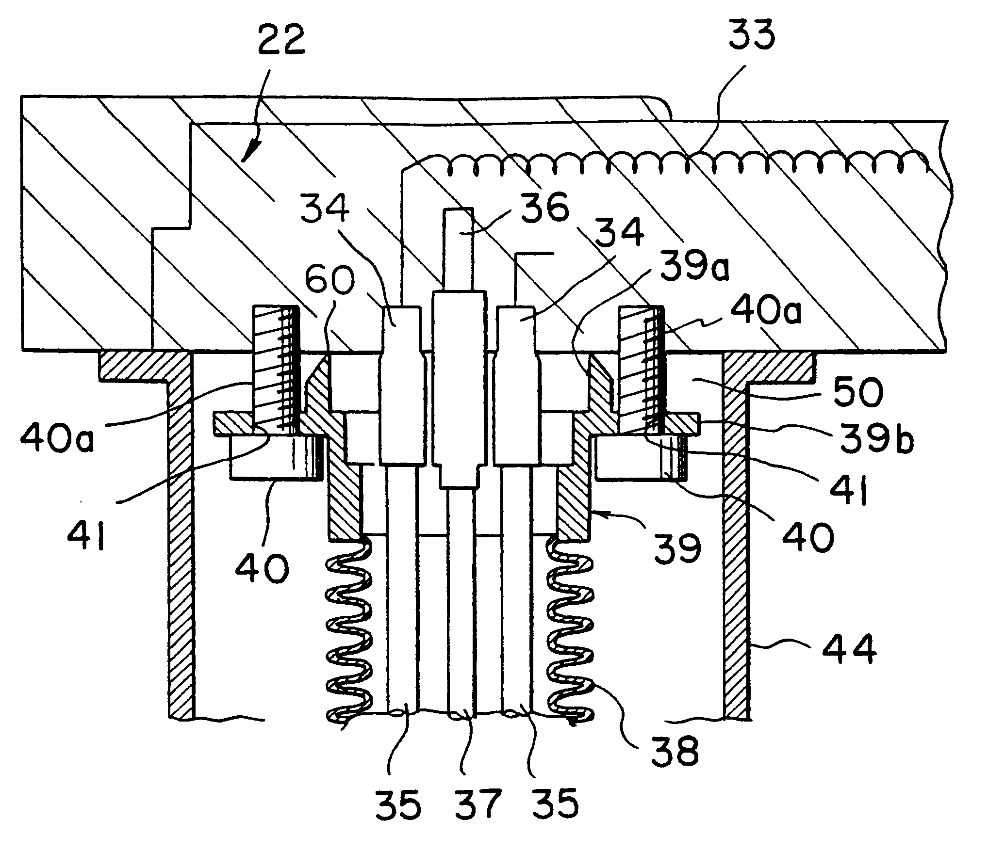
Since this invention uses an engagement means to connect the sheath to the susceptor, it is more difficult for heat to escape to the metal tube from the susceptor that has been heated to a predetermined temperature by the resistance heater, than the prior-art connection provided by gold-soldering, making it possible to improve the uniformity of the temperature distribution over the surface of the susceptor and thus improve the uniformity of the processing of the object.
The engagement means may be configured of a screw shaft, where the screw shaft is inserted only partially into the surface of the susceptor, and a space is formed between the end piece and the surface of the susceptor. Thus the provision of this space makes it possible to reliably prevent heat from escaping from the susceptor to the sheath.
The seating portion may be provided with a hole through which the engagement means passes, where this hole has dimensions such that the engagement means passes loosely therethrough. The use of such a configuration makes it possible to permit thermal expansion of the sheath, making it more difficult for the connective portion between the sheath and the susceptor to be damaged, than the prior-art gold-soldering.
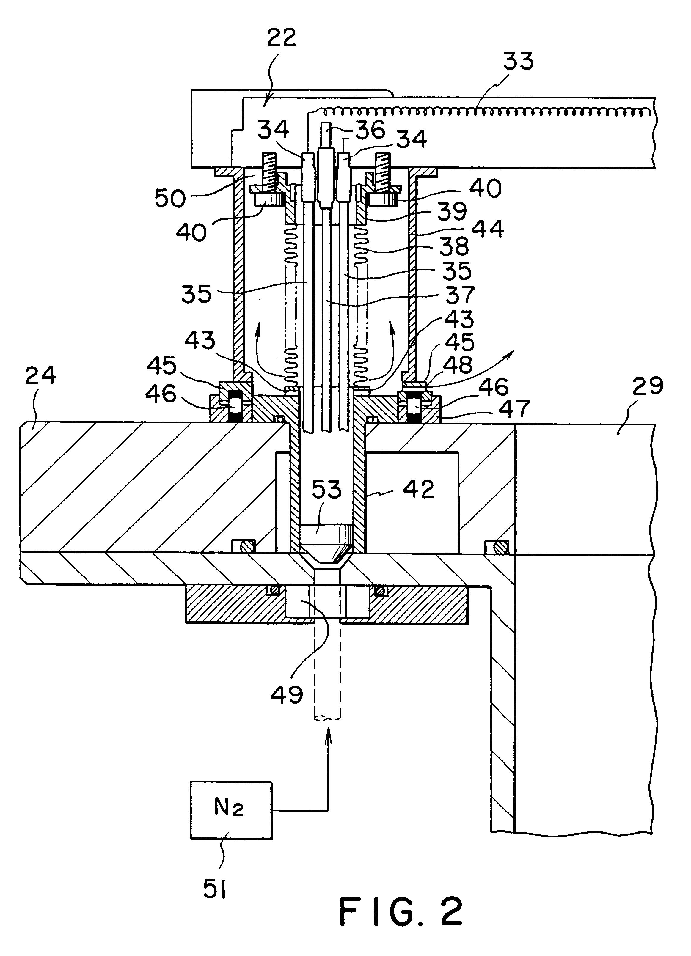
A corrosion-resistant tube made of a non-metallic material may be interposed between the surface of the susceptor and the wall of the processing chamber, surrounding the sheath with a space therebetween. This configuration makes it possible to protect the sheath from the highly corrosive cleaning gases during the cleaning. In addition, the cleaning gases do not leak into the interior of the sheath, preventing corrosion of the power lines and suppressing the generation of particles.
The configuration may also be such that an inert gas is supplied into the interior of the sheath. This ensures that the interior of the sheath is purged with the inert gas, making it possible to prevent the dispersion of the highly-corrosive cleaning gases back into the sheath. By allowing the inert gas to flow out from the sheath into the space between the sheath and the corrosion-resistant protective tube, the environment around the sheath can be made an inert gas environment, making it possible to prevent corrosion even further. By allowing the inert gas to flow out even further from the space between the sheath and the corrosion-resistant protective tube into the processing chamber, it is possible to completely prevent corrosion.

Problems solved by technology

Thus the surface temperature distribution of the ceramic member 1 becomes uneven and, as a result, the uniformity of the film formed during the film-formation process is adversely affected.
However, the gold-soldered portions of the molybdenum ring member 8 will become damaged by the thermal cycles during the film formation and the cleaning, and also these gold-soldered portions will be corroded by the cleaning gases, such as ClF.sub.3 and NF.sub.3, used in the cleaning.
This means that the cleaning gases such as ClF.sub.3 and NF.sub.3 will leak into the ring member 8 through the thus damaged or corroded gold-soldered portions and be dispersed therein, causing corrosion and peeling of the molybdenum ring member 8 as well, and also causing corrosion of the terminals 3 and the power lines 4.
As a result, there is a danger of particles being generated.
The use of such a configuration makes it possible to permit thermal expansion of the sheath, making it more difficult for the connective portion between the sheath and the susceptor to be damaged, than the prior-art gold-soldering.

Method used


Image

  • Gas processing apparatus for object to be processed
  • Gas processing apparatus for object to be processed
  • Gas processing apparatus for object to be processed

Examples


example

Measurements were made of the temperature distribution within the surface of a ceramic heater to which the present invention was applied. For comparison, measurements were also made of the temperature distribution within the surface of a ceramic heater of the prior-art configuration with gold-soldering, as shown in FIG. 13.

During the measurement of in-surface temperature distributions, both the embodiment of this invention and the comparative example had a set heater temperature of 600.degree. C. and a pressure within the processing chamber of 150 mTorr. The results of these measurements are shown in FIG. 6A for the comparative example and FIG. 6B for the example of this invention. The values shown in FIGS. 6A and 6B illustrate the differences between "uniform temperatures at nine measurement points" and "the temperature at each measurement point." The results show that the in-surface temperature distribution of this embodiment of the present invention is suppressed to + / -0.63%, in ...


PUM

PropertyMeasurementUnit
Electrical resistanceaaaaaaaaaa
Corrosion propertiesaaaaaaaaaa
Dimensionaaaaaaaaaa

Abstract

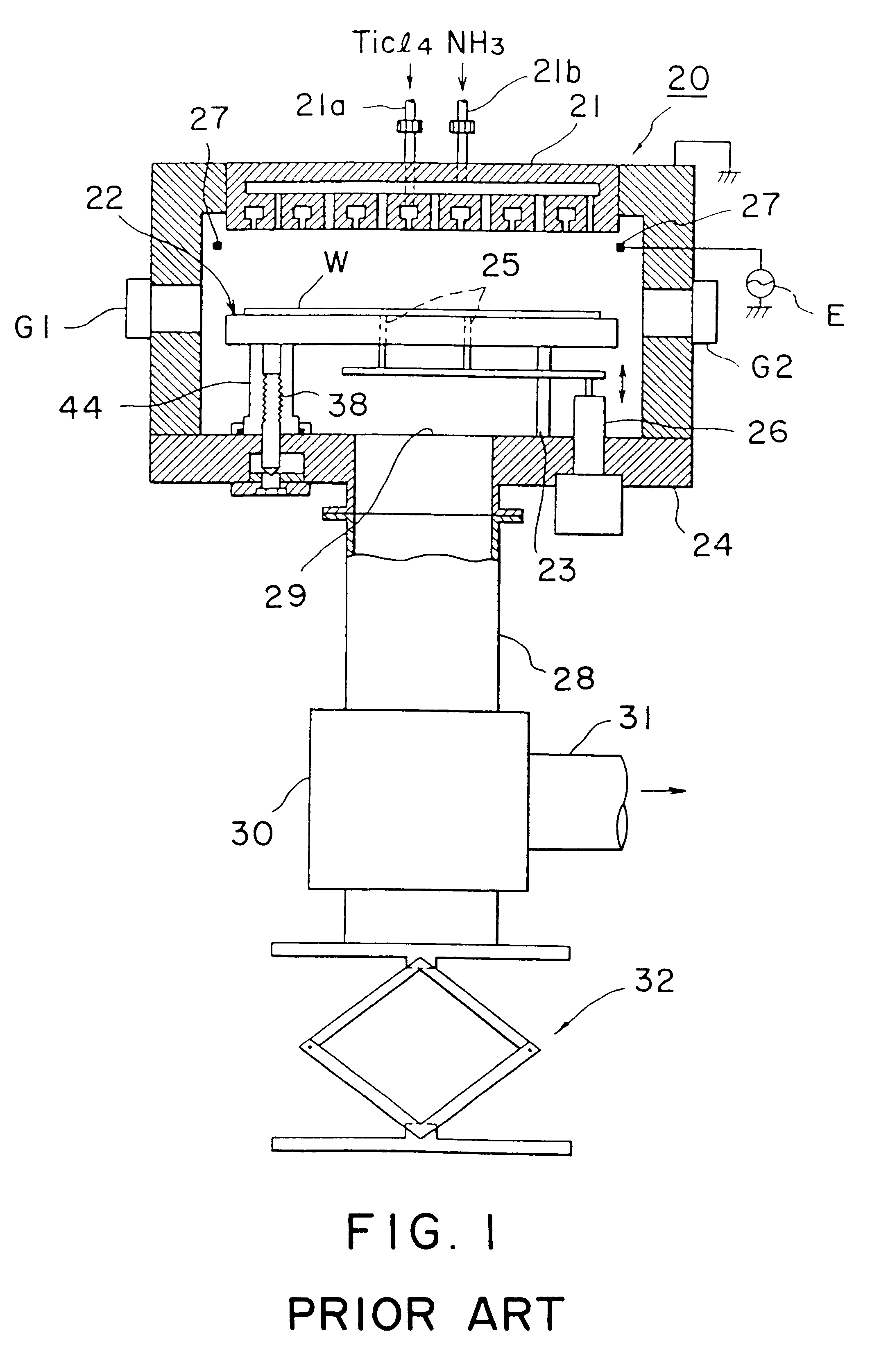
A resistance heating element 33 for heating a wafer W is embedded within a ceramic heater 22 that forms a susceptor for a semiconductor wafer W to be processed, and power lines 35 from the resistance heating element 33 extend out of the processing chamber 20. A sheathing bellows 38 that houses the power lines 35 in an insulated state is interposed between the ceramic heater 22 and a base plate 24 of the processing chamber 20, and an end piece 39 of the sheathing bellows 38 is connected by screws 40 to the ceramic heater 22 to provide a space 50 therebetween. The screws 40 are such as to permit the thermal expansion of the sheathing bellows 38. This configuration makes it possible to make the temperature distribution in the surface of the semiconductor wafer uniform and thus improve the uniformity of film formation, and also prevent corrosion of components such as the power lines and terminals, and suppress the generation of particles.

Description

1. Field of the InventionThe present invention relates to a gas processing apparatus for an object to be processed which ensures that the temperature distribution within a surface of an object to be processed, such as a semiconductor wafer, is more even and thus improves the uniformity with which a film is formed thereon, and which also makes it possible to prevent corrosion of components such as power lines and terminals, and suppress the generation of particles.2. Description of Related ArtDuring the process of fabricating a semiconductor device, film-formation processes such as chemical vapor deposition (CVD) or sputtering are performed to fabricate an integrated circuit on a semiconductor wafer of a material such as silicon (hereinafter referred to simply as "wafer"). To form a thin film uniformly over a wafer in such a film-formation process, it is necessary to heat the entire surface of the wafer to a predetermined temperature, then maintain that temperature.One method of heat...

Claims


Application Information

Patent Timeline
IPC IPC(8): C23C16/458H01L21/00
CPCH01L21/67103C23C16/4586
Inventor FUTAMURA, MUNEHISAIWATA, TERUO
Owner TOKYO ELECTRON LTD
Learn More