
Method of molding ophthalmic lens product, and mold assembly used in the method

a technology of ophthalmic lenses and molds, which is applied in the direction of foundry moulding equipment, instruments, foundry patterns, etc., can solve the problems of not providing the intended contact lens with high configuration accuracy, the optical surface of the lens product does not have high configuration accuracy, and the quantity of monomer composition supplied to the mold cavity is not sufficien

Inactive Publication Date: 2002-03-12
MENICON CO LTD
View PDF8 Cites 11 Cited by
  • Summary
  • Abstract
  • Description
  • Claims
  • Application Information

AI Technical Summary

Benefits of technology

In the above method of the present invention, the liquid monomer composition in the mold cavity is polymerized under application of a pressure higher than the atmospheric pressure directly to the liquid surface of the monomer composition accommodated in the monomer storage space which is held in fluid communication with the mold cavity. Owing to the pressure applied to the mass of the monomer composition in the monomer storage space in the mold assembly, the monomer composition present in the storage space is fed into the mold cavity via a passage formed in the mold assembly, to thereby effectively compensate for a volume of shrinkage of the monomer composition in the mold cavity during its polymerization. According to this arrangement, the optical surfaces of the lens product have a significantly enhanced accuracy of configuration without being adversely affected by the polymerization shrinkage of the monomer composition.
Although the monomer storage space in the mold assembly constructed as described above is open to the external space, the evaporation of the monomer composition is minimized by applying a suitable pressure higher than the atmospheric pressure to the monomer composition accommodated in the storage space. Further, the monomer composition is polymerized at a relatively low temperature in a range of 10-80.degree. C., to thereby effectively prevent the evaporation of the monomer composition, as compared when the monomer composition is polymerized at a relatively high temperature according to the conventional methods. Accordingly, the polymer product to be obtained does not suffer from a variation in its composition, in other words, the lens product to be obtained does not suffer from a variation of its properties, so that the lens product has an intended high quality.
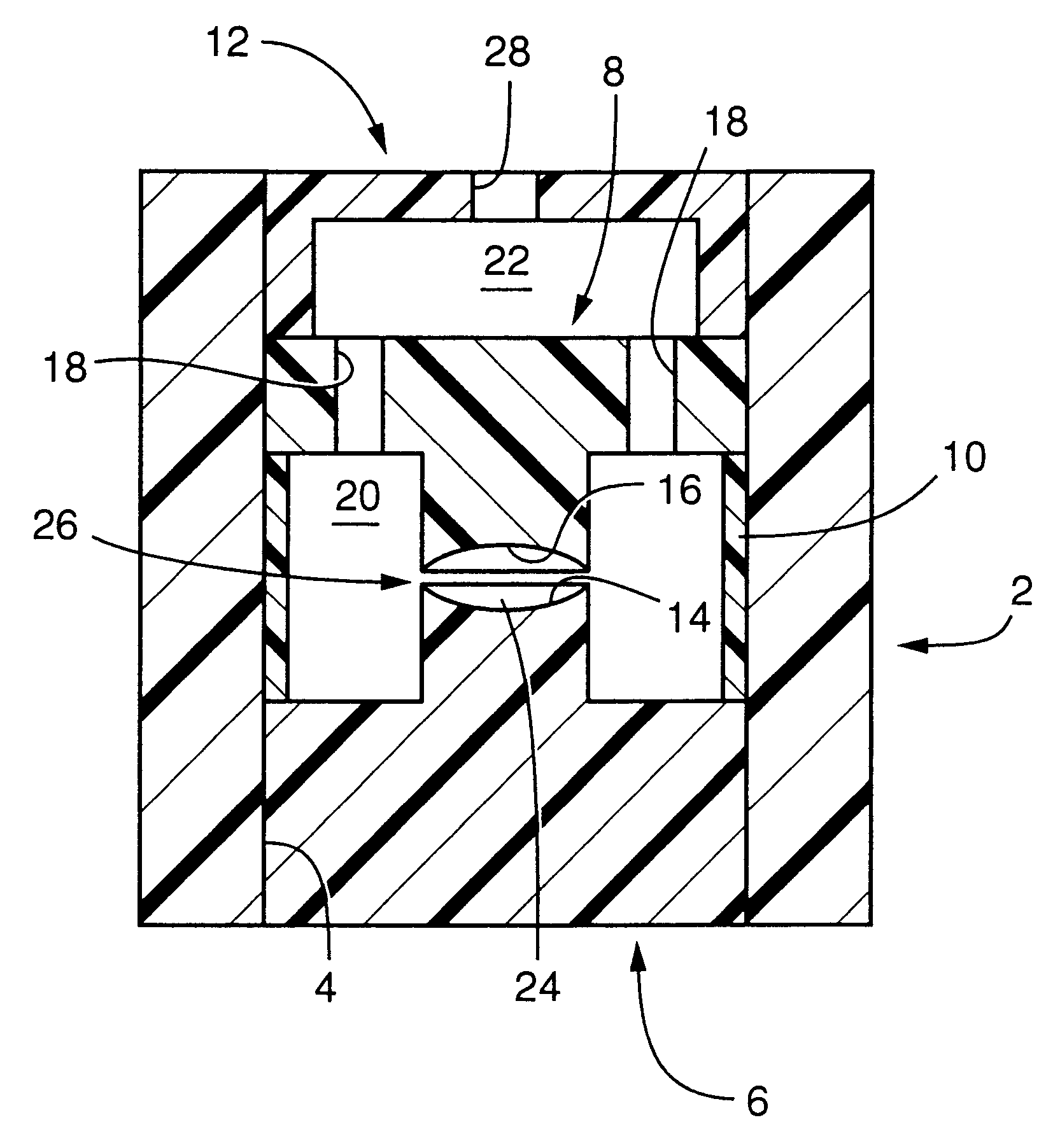
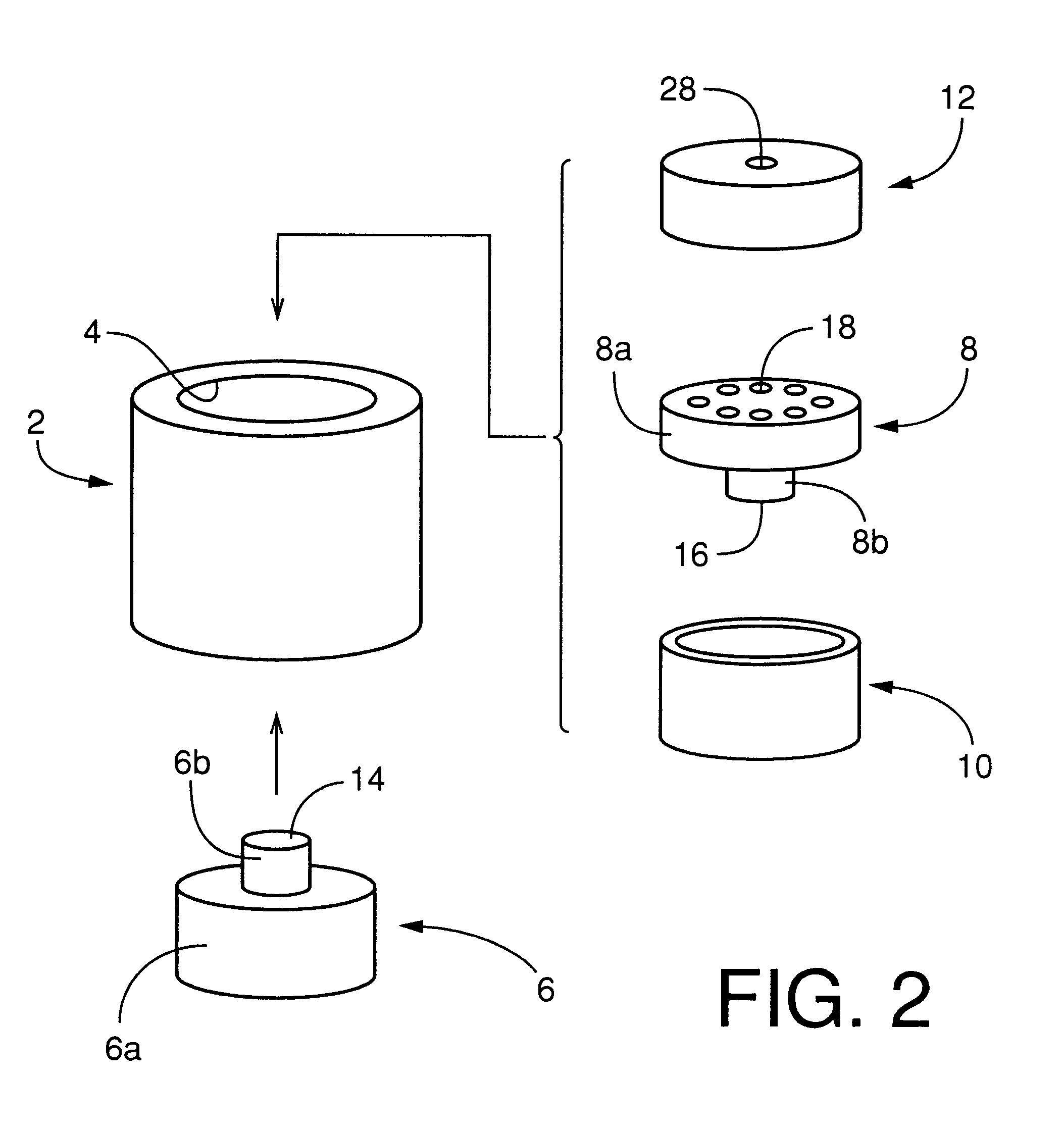
In the mold assembly constructed as described above, the mold cavity is filled with the monomer composition fed from the intermediate chamber via the plurality of through-holes formed through the upper base portion of the upper mold half, while the intermediate chamber and the mold cavity are deaerated via the through-holes. Thus, the through-holes of the present mold assembly serve as not only monomer inlet holes, but also deaerating holes. The present mold assembly does not require any light shielding means for protecting any portion of the monomer composition against exposure to a radiation used for the polymerization and any mechanism for removing the molded polymer product from the mold assembly, as provided in the conventional mold assembly, resulting in a simplified structure of the mold assembly. In the mold assembly used in the present invention, the plurality of through-holes are formed through the upper base portion of the upper mold half, such that the through-holes are equiangularly spaced from each other in the circumferential direction of the upper base portion, that is, in the circumferential direction of the mold cavity, to thereby permit a uniform or even flow of the monomer composition into the molding cavity via the through-holes. In addition, the intermediate chamber surrounding the mold cavity and filled with the monomer composition assures an effective flow of the monomer composition into the mold cavity, resulting in even or uniform supply of the monomer composition into the mold cavity to compensate for the shrinkage of the monomer composition during its polymerization. Accordingly, the lens product to be obtained has improved surface consistency.

Problems solved by technology

According to this arrangement, the monomer composition may not be supplied to the mold cavity in an amount sufficient to compensate for its polymerization shrinkage in the mold cavity.
Thus, in the method disclosed in the above-indicated U.S. patents, the optical surfaces of the lens product do not have high accuracy of configuration.
This arrangement wherein the profiles of the molding surfaces change during the polymerization of the monomer may not provide the intended contact lens with high accuracy of configuration.
On the other hand, if the molding surfaces deflect or deform so as to be in contact with the monomer composition in the mold cavity which shrinks during the polymerization, the mold assembly may suffer from a problem similar to that experienced in the above U.S. Pat. No. 5,578,332.
In other words, the intraocular lens to be obtained by using the mold assembly does not have optical surfaces with high accuracy of configuration due to the deflection or deformation of the molding surfaces.
If the number of the through-holes 18 is smaller than three, the amount of the monomer composition to be supplied to the mold cavity to compensate for its polymerization shrinkage in the mold cavity is insufficient.
In this case, the molded surfaces of the obtained lens product do not have profiles which exactly follow those of the lower and upper molding surfaces 14, 16, respectively, due to the insufficient supply of the monomer composition, resulting in uneven surfaces of the obtained lens product.

Method used


Image

  • Method of molding ophthalmic lens product, and mold assembly used in the method
  • Method of molding ophthalmic lens product, and mold assembly used in the method
  • Method of molding ophthalmic lens product, and mold assembly used in the method

Examples


Embodiment Construction

To further clarify the concept of the present invention, there will be described one example of the invention. It is to be understood that the present invention is not limited to the details of the illustrated example.

A plurality of ophthalmic lens products were prepared by using respective mold assemblies shown in FIGS. 1 and 2, in the following manner.

Initially, a monomer composition (30) was prepared by using 70 parts by weight of phenoxyethyl acrylate, 30 parts by weight of ethyl acrylate, 15 parts by weight of 2-hydroxyethyl methacrylate, 4 parts by weight of butanediol diacrylate as the cross-linking agent, and 0.5 part by weight of 2,2'-azobis(2,4-dimethyl valeronitrile) as the radical polymerization initiator. The thus prepared monomer composition (30) was introduced into the upper chamber (22) of each mold assembly, so that the monomer composition (30) is fed into the intermediate chamber (20) via the through-holes (18), and is then fed into the mold cavity (24) via the cir...


PUM

PropertyMeasurementUnit
Temperatureaaaaaaaaaa
Pressureaaaaaaaaaa
Pressureaaaaaaaaaa

Abstract

A method of molding an ophthalmic lens product by using a mold assembly which has a mold cavity, the lens product having a configuration corresponding to that of an ophthalmic lens or a precursor of the ophthalmic lens and being obtained by polymerizing a liquid monomer composition in the mold cavity to provide a polymer product which gives the lens product, the method comprising the steps of: preparing the mold assembly having a monomer storage space for storing the liquid monomer composition, which storage space is held in fluid communication with the mold cavity; filling the mold cavity of the mold assembly with the liquid monomer composition while the liquid monomer composition is accommodated in the monomer storage space; and polymerizing the liquid monomer composition at a temperature of 10-80° C. while a pressure higher than the atmospheric pressure is applied directly to a liquid surface of a mass of the liquid monomer composition accommodated in the monomer storage space.

Description

The present application is based on Japanese Patent Application No. 10-172572 filed Jun. 19, 1998, the content of which is incorporated hereinto by reference.1. Field of the InventionThe present invention relates in general to molding of an ophthalmic lens product by using a mold assembly which has a mold cavity. In particular, the invention is concerned with the method of molding such a lens product having a configuration corresponding to that of the ophthalmic lens such as an intraocular lens or a contact lens, or a configuration corresponding to that of a precursor of the ophthalmic lens, by polymerizing a monomer composition in the mold cavity to provide a polymer product which constitutes the lens product.2. Discussion of the Related ArtThere have been known various methods for forming an ophthalmic lens product having a configuration or geometry corresponding to that of an ophthalmic lens such as an intraocular lens or a contact lens, or a configuration corresponding to that o...

Claims


Application Information

Patent Timeline
IPC IPC(8): B29C31/04B29C33/00B29C39/24B29D11/02B29D11/00G02C7/02B29C39/40
CPCB29C31/04B29C33/0061B29C39/24B29D11/00432B29D11/023B29D11/00317B29C2043/3618Y10S425/808B29K2105/0002B29L2011/0041B29D11/00009B29D11/00038B29D11/0048B29D11/00538
Inventor OJIO, TATSUYANIWA, KAZUHARUYAMASHITA, KEIJIYASUDA, AKIHIRO
Owner MENICON CO LTD
Learn More