
Configurable over-temperature protection circuit applied to switching power supply

A technology of over-temperature protection circuit and switching power supply, applied in emergency protection circuit devices, emergency protection devices with automatic disconnection, circuit devices, etc., can solve problems such as hazards, chip damage, long-term high temperature, etc., to improve the application range and improve The effect of configuration precision

Active Publication Date: 2018-02-23
BEIJING MXTRONICS CORP +1
View PDF11 Cites 2 Cited by
  • Summary
  • Abstract
  • Description
  • Claims
  • Application Information

AI Technical Summary

Problems solved by technology

[0002] The power consumption of switching power supply is generally very low, but after the adjustment tube in the circuit is packaged, as a heating element, it may appear high temperature for a long time under load, causing damage to the chip, so it is necessary to design an over-temperature protection circuit to prevent Cause thermal damage to other parts of the chip, or even cause greater harm
[0003] The over-temperature point of the existing over-temperature protection circuit cannot be changed according to the needs of the application environment, which limits the application range of the over-temperature protection circuit

Method used


Image

  • Configurable over-temperature protection circuit applied to switching power supply
  • Configurable over-temperature protection circuit applied to switching power supply
  • Configurable over-temperature protection circuit applied to switching power supply

Examples


Embodiment Construction

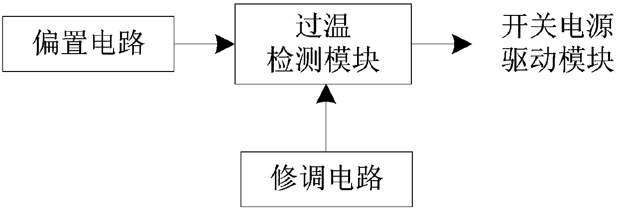
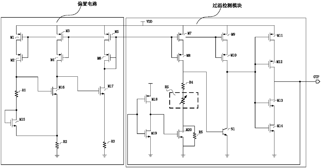
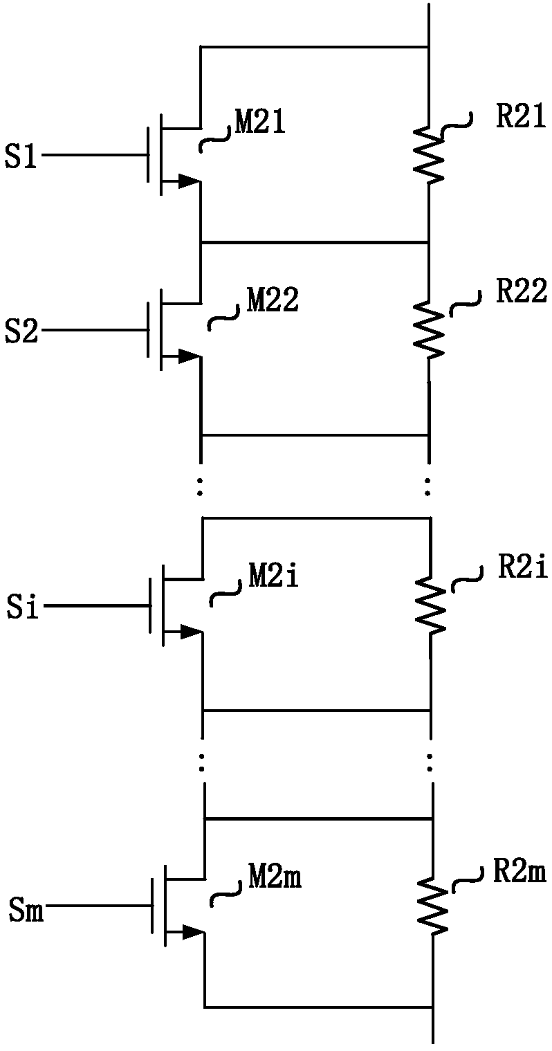
[0026] figure 1 It is a system block diagram of the over-temperature protection circuit of the present invention, including a bias circuit, an over-temperature detection module, and a trimming circuit. Under the action of the power supply voltage, the bias circuit obtains a bias current that has nothing to do with the power supply voltage, and outputs it to the over-temperature detection module, the power supply voltage is the working voltage of the switching power supply. The trimming circuit receives the power supply voltage and the trimming voltage input from the outside, obtains a trimming signal according to the trimming voltage, and outputs it to the over-temperature detection module. The over-temperature detection module receives the power supply voltage, the bias current output by the bias circuit and the trimming signal output by the trimming circuit, and outputs a high level to the switching power supply drive module according to the power supply voltage and the bias...


PUM


Abstract

The invention relates to a configurable over-temperature protection circuit applied to a switching power supply. The configurable over-temperature protection circuit is composed of a biasing circuit,an over-temperature detection module, and a trimming circuit. The biasing circuit obtains a biasing current independent of a power supply voltage under the effect of the power supply voltage and outputs the biasing current to the over-temperature detection module; and the trimming circuit receives the power supply voltage and an externally inputted trimming voltage, obtains a trimming signal, andoutputs the trimming signal to the over-temperature detection module. The over-temperature detection module receives the power supply voltage and the biasing current and adjusts the detection resistance in the over-temperature detection module based on the trimming signal to adjust an over-temperature point; when the ambient temperature exceeds the over-temperature point, state overturning is carried out on an over-temperature protection signal outputted to a switching power supply drive module and thus the switching power supply circuit is turned off. According to the configurable over-temperature protection circuit, over-temperature point configuration can be carried out based on a practical application environment; and the over-temperature point configuration precision can be set. The over-temperature point can be configured dynamically based on needs of application environments, so that the application range and the configuration precision of the over-temperature protection circuitare improved.

Description

technical field [0001] The invention relates to an over-temperature protection circuit, in particular to a configurable over-temperature protection circuit applied in a switching power supply with a wide temperature range, and belongs to the field of switching power supply protection circuits. Background technique [0002] The power consumption of switching power supply is generally very low, but after the adjustment tube in the circuit is packaged, as a heating element, it may appear high temperature for a long time under load, causing damage to the chip, so it is necessary to design an over-temperature protection circuit to prevent Cause thermal damage to other parts of the chip, and even cause greater harm. [0003] The over-temperature point of the existing over-temperature protection circuit cannot be changed according to the requirements of the application environment, which limits the application range of the over-temperature protection circuit. Contents of the inve...

Claims


Application Information

Patent Timeline
IPC IPC(8): H02H5/04H02H7/12
CPCH02H5/04H02H7/12
Inventor 宋奎鑫莫艳图孔瀛姜爽喻贤坤李卓王佳王莉穆辛徐小倩彭斌樊旭刘松林王潇潇王艳翔毛鹤莉
Owner BEIJING MXTRONICS CORP
Learn More