
Monolithically bonded construct of rare-earth magnet and metal material and method for bonding same

a rare-earth magnet and metal material technology, applied in the direction of magnetic bodies, non-electric welding apparatuses, magnetic circuit shapes/forms/constructions, etc., can solve the problems of inferior strength, bending, torsion, and general brittleness of rare-earth magnets, and achieve the effect of improving the bonding strength between rare-earth magnets

Inactive Publication Date: 2001-12-18
MEIDENSHA ELECTRIC MFG CO LTD +1
View PDF8 Cites 36 Cited by
  • Summary
  • Abstract
  • Description
  • Claims
  • Application Information

AI Technical Summary

Problems solved by technology

Conventionally known magnets containing rare-earth elements (hereinafter referred to rare-earth magnets) are generally brittle and inferior in strength against tension, bending, torsion and the like and in machinability.
Furthermore, there is a problem that it is difficult to increase bonding strength between these rare-earth magnets and metals of rotor member such as electric motor and the like.
However, the following problems exist.
First of all, rare-earth magnets made by powder sintering method are inherently brittle materials, and insufficient in mechanical characteristics such as strength, tenacity, toughness and deformative capability, as compared with iron core and other metal materials constituting a rotor.
Therefore, if centrifugal force, which acts on a rotor, increases further by the speedup or increase of capacity of electric machines and the like, there arises a problem that a rare-earth magnet tends to deform or break.
Furthermore, the presence of internal defects, such as voids and small cracks, contained in a magnet prepared by a powder sintering in an argon gas atmosphere under a normal or somewhat vacuum pressure is considered to be one of the causes that make powder sintering magnets lower in strength.
Secondly, it can be said that rare-earth magnets are insufficient in corrosion resistance.
Thus, if these rare-earth magnets are allowed to stand still for several days in the atmosphere, their surface will have a different color and their corrosion will proceed.
Thirdly, it can be said that bonding strength between a rare-earth magnet and a rotor member metal is insufficient.
Therefore, bonding strength can hardly be expected in a rotor portion that generates heat to have a temperature of at least 100.degree. C. when it is driven.
Fourthly, it can be said that high-strength bonding technique, which does not deteriorate magnetic characteristics of rare-earth magnets, has not yet been established.
That is, it is the actual condition that high-strength bonding technique between magnet and rotor member metal, which can endure a temperature higher than 100.degree. C. caused by heat generated by a rotor, without deteriorating magnetic characteristics of rare-earth magnets in themselves, has not yet been established.
Thus, it is extremely difficult to bond them without deteriorating magnetic characteristics of the magnets.
There is a problem that silver element as a brazing filer metal diffuses deep into the inside of Nd--Fe--B magnet, and thus coercivity of the magnet lowers greatly.
Therefore, it is easily oxidized by a reaction with oxygen, and there arise problems that the resultant oxide comes off the bonded portion, thereby to lower the bonding strength, and surrounding devices are contaminated.
Furthermore, the bonding member in itself contains a large amount of rare-earth element of high price.
Thus, there is a problem that the raw material cost increases.
Therefore, in case that the surfaces to be bonded together are curved surfaces, it is difficult to uniformly pressurize the entire surfaces.
Furthermore, for example, in case that a supporting member is bonded to the entire peripheral surface of a cylindrical magnet, this method can not be adopted.
Thus, there is a problem that the shape of an object to be bonded is limited.
It is impossible to directly apply them to rare-earth magnets that are completely different therefrom in texture and condition.
Therefore, voids existing in conventional magnet materials are compressed and broken.

Method used


Image

  • Monolithically bonded construct of rare-earth magnet and metal material and method for bonding same
  • Monolithically bonded construct of rare-earth magnet and metal material and method for bonding same
  • Monolithically bonded construct of rare-earth magnet and metal material and method for bonding same

Examples


Embodiment Construction

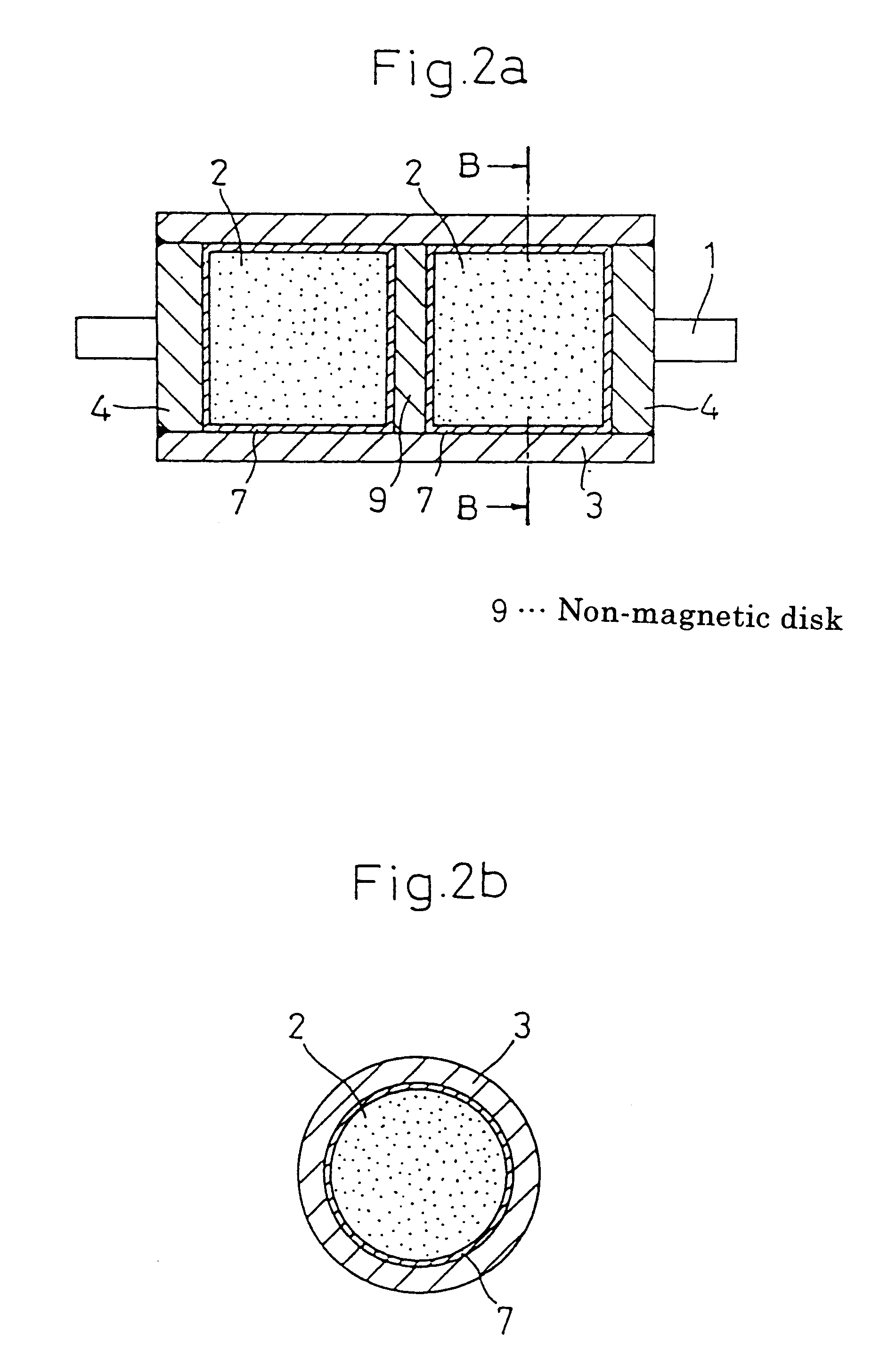
In the following, examples of the present invention will be explained, based on concrete data. In the present example, a rotor structure sample shown in the above-mentioned FIG. 2 was made, and a solid-phase diffusion bonding experiment was conducted by the HIP treatment in case that the intermediate member was interposed therebetween.

1. [Test Material]

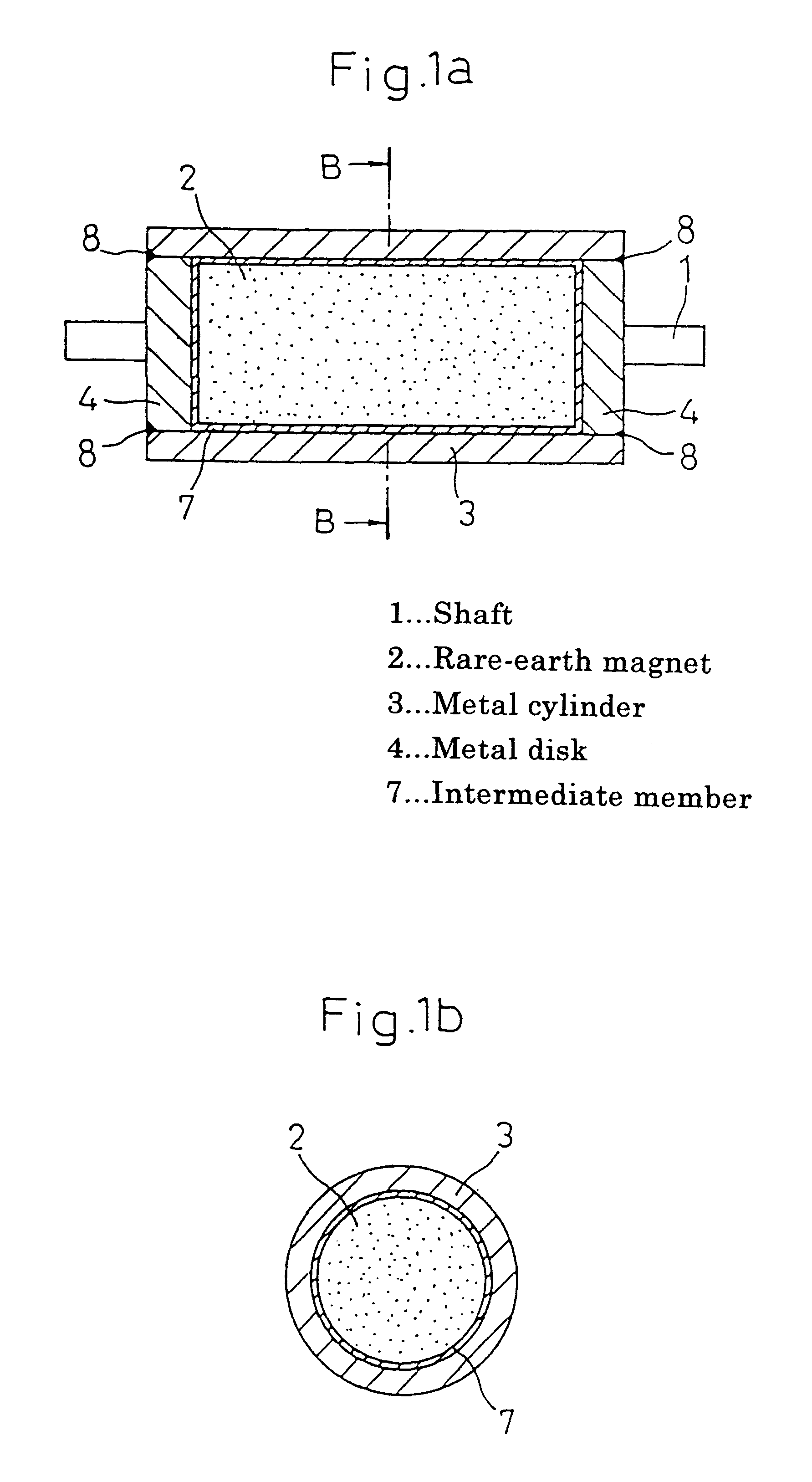
As a test material, a rare-earth magnet 2, a columnar Nd--Fe--B sintered magnet (the above-mentioned NEOMAX-35H) having dimensions of .phi.10.0.times.10 mm under non-magnetized condition was used. A 6Al--4V titanium alloy annealed material having an inner diameter of .phi.10.2 mm, an outer diameter of 16.2 mm, a thickness of 3 mm, and a length of 35 mm was used for a non-magnetic metal cylinder 3. A 6Al--4V titanium alloy disk annealed material having dimensions of .phi.10.1 mm.times.5 mm was used for non-magnetic metal disks 4,4 and a non-magnetic disk 9.

A high melting-point metal thin sheet having a thickness of 50 .mu.m was used as...


PUM

PropertyMeasurementUnit
Fractionaaaaaaaaaa
Fractionaaaaaaaaaa
Timeaaaaaaaaaa

Abstract

Its basic means is a monolithically bonded construct prepared by monolithically bonding together a rare-earth magnet 2 and a an alloy material that is a high melting point metal or a high specific-tenacity material through the solid phase diffusion bonding by the hot isostatic pressing treatment, and a monolithically bonded construct with an interposal of a thin layer of the high melting point metal between a rare-earth magnet 2 and an alloy material 3, 4 that is a high specific-tenacity material. As a method for the bonding, there is used a hot isostatic pressing treatment method in which a rare-earth An magnet and a high melting-point metal are laminated together, thereby to prepare an object to be treated, then the object is put into a hermetic-type high pressure container having an inner wall portion equipped with a heater, then the object is uniformly pressurized in all directions by a synergistic effect caused by pressure and temperature, while the object is maintained for a certain period of time under a certain pressure and temperature condition in an atmosphere of an inert gas, thereby to monolithically bond the object. With this, it is possible to obtain a bonded construct in which a magnet can monolithically be bonded with another metal member with a high strength, without deteriorating magnetic characteristics, such that the rare-earth magnet's insufficiency in brittleness, rigidity, tenacity and the like is compensated.

Description

The present invention relates to monolithically bonded constructs of various rare-earth magnets and metal materials and methods for bonding the same.BACKGROUND TECHNIQUEConventionally known magnets containing rare-earth elements (hereinafter referred to rare-earth magnets) are generally brittle and inferior in strength against tension, bending, torsion and the like and in machinability. Furthermore, there is a problem that it is difficult to increase bonding strength between these rare-earth magnets and metals of rotor member such as electric motor and the like. For example, an example of a schematic structure of a rotor used in a permanent magnet type high-speed electric generator, motor or the like, in which a rare-earth magnet is used, will be explained, by reference to FIGS. 46a and 46b. In these drawings, 1, 2, 3 and 4, 4 are a shaft, a rare-earth magnet, a metal cylinder of non-magnetic material, and a metal disk of non-magnetic material, respectively.The above rare-earth magn...

Claims


Application Information

Patent Timeline
IPC IPC(8): B23K20/16B23K20/02H01F1/057H01F41/02H01F1/032H02K1/02H02K1/00H02K1/27H01F1/055H02K15/03
CPCB23K20/021B23K20/16H01F1/055H01F1/057H01F41/026H02K1/02H02K1/2726H02K1/278H02K15/03B23K20/023Y10T428/12931Y10S428/928Y10T428/12465Y10T428/12979Y10T428/12076Y10T428/12944Y10T428/12806Y10T428/12951H01F7/02
Inventor KOGA, MASAKISUZUKI, NOBUTAKASAITOH, HITOSHIOYAMADA, KENSHIROTOKUHARA, KOKIMINO, SHUJIISHIGAKI, NAOYUKIYAMAMOTO, HITOSHI
Owner MEIDENSHA ELECTRIC MFG CO LTD
Learn More