
Combustion process and apparatus therefore containing separate injection of fuel and oxidant streams

a combustion process and separate injection technology, applied in the direction of combustion types, combustion using lump and pulverulent fuel, lighting and heating apparatus, etc., can solve the problems of inability to eliminate poor quality of products manufactured with material melted in such a furnace, and inability to achieve the effect of eliminating all nitrogen from the furnace in practi

Inactive Publication Date: 2001-12-18
AIR LIQUIDE AMERICA INC
View PDF41 Cites 59 Cited by
  • Summary
  • Abstract
  • Description
  • Claims
  • Application Information

AI Technical Summary

Benefits of technology

Additionally, it is an object of the present invention to provide a combustion method that generate flames with low peak temperatures, and thus reduce the emissions of nitrogen oxides by the combustion process.
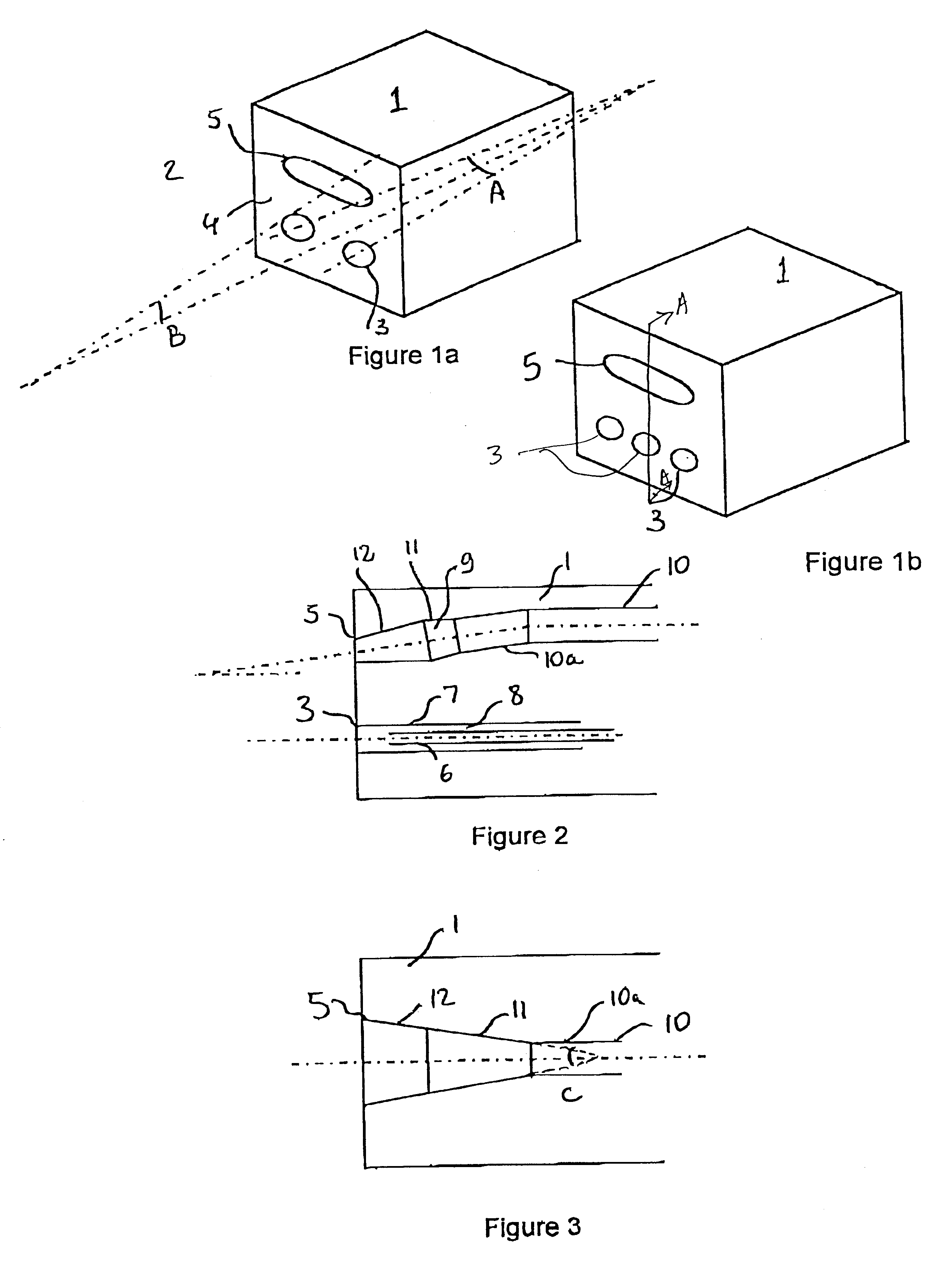
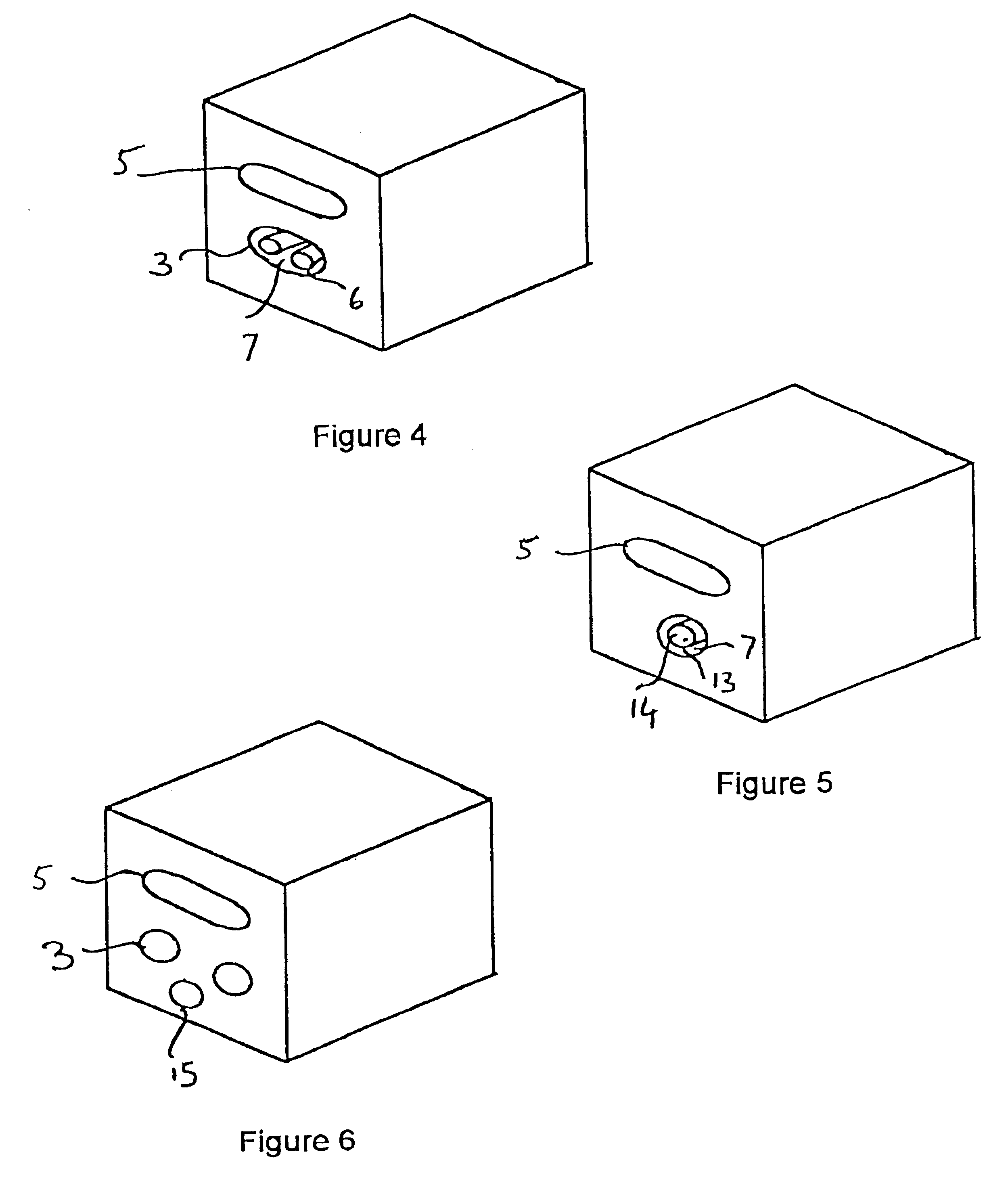
c) a metallic burner assembly attached to the refractory block by means of said mounting bracket, the metallic burner assembly comprising at least one oxidant inlet, and at least two oxidant outlets, the first oxidant outlet opening on said cavity for injection of the main oxidant, the second oxidant outlet supplying secondary oxidant to the at least one cavity for injection of fuel to initiate the combustion of the fuel close to the hot face of the refractory block, the secondary oxidant further creating a protective layer of oxidant gas along the inside walls of the at least one fuel cavity that prevents chemical reactions between the refractory block material and the fuel that would eventually damage the burner block,

Problems solved by technology

Otherwise, hot and cold regions may co-exist in the furnace, which is not desirable.
The quality of products manufactured with material melted in such a furnace is often poor.
Also, it is impossible in practice to eliminate all nitrogen from a furnace, because industrial furnaces are not tight to air leaks, the fuel usually contains some nitrogen, and oxygen from non-cryogenic sources, such as oxygen produced by a Vacuum Swing Adsorption plant (VSA) contains a small residual nitrogen concentration.
As a consequence of the high temperatures encountered in melting furnaces, one important drawback of these burners is the need for cooling, usually a jacket where a circulating fluid such as water provides the cooling.
Severe corrosion problems for the cooling jacket can arise particularly when the furnace atmosphere contains condensable vapors.
Thus, the flame is confined in and directed by the cylindrical cavity as a narrow axisymmetric jet, and provides insufficient covering of the melt in the furnace.
Another drawback of these gas cooled burners is that the flame may overheat and damage the furnace refractory wall because it starts in the wall itself.
Also recirculation zones under the flame itself tend to accelerate refractory wear when the furnace atmosphere chemically reacts with the refractory material of the furnace wall which may reduce the furnace lifetime.
Another drawback of these burners is that they are mechanically complex to build in order to obtain a flat flame.
However, the flame of such a burner has a high peak temperature and large quantities of nitrogen oxides are created in the furnace.
It is, thus, extremely difficult for a furnace operator to determine and / or control the location of the combustion zones, and whether or not the burner apparatus is actually turned on, which may be hazardous.
Another drawback of this burner is that the entrainment of combustion products promotes strong recirculation streams of gases in the furnace, which in turn accelerates the wear of the refractory walls of the furnace.
With this technique, the flame temperature is increased, which results in higher nitrogen oxide formation.
As mentioned before, this promotes strong recirculation streams of gases in the furnace, which in turn accelerates the wear of the refractory walls of the furnace.
Also, the use of high velocity oxidant jets requires the use of a high pressure oxidant supply, which means that the oxidant gas needs to be either produced or delivered at high pressure (the fuel gas is usually at relatively high pressure) or that the oxidant gas, such as the low pressure oxygen gas usually supplied by a VSA unit, has to be recompressed before being injected into the furnace.
Such situations are known to occur for unstable flames that are deflected by the complex flow pattern of the combustion products in a furnace.
For example, low momentum burners where the fuel and oxidant are injected at a low velocity in a furnace, overcome the drawbacks related earlier of high velocity burners, but tend to produce unstable flames.

Method used


Image

  • Combustion process and apparatus therefore containing separate injection of fuel and oxidant streams
  • Combustion process and apparatus therefore containing separate injection of fuel and oxidant streams
  • Combustion process and apparatus therefore containing separate injection of fuel and oxidant streams

Examples


Embodiment Construction

The term "fuel", according to this invention, means, for example, methane, natural gas, liquefied natural gas, propane, atomized oil or the like (either in gaseous or liquid form) at either room temperature (about 25.degree. C.) or in preheated form. The term "oxidant", according to the present invention, means a gas containing oxygen that can support combustion of the fuel. Such oxidants include air, oxygen-enriched air containing at least 50% vol. oxygen such as "lndustrially" pure oxygen (99.5%) produced by a cryogenic air separation plant, or non-pure oxygen produced for example by a vacuum swing adsorption process (about 88% vol. oxygen or more) or "impure" oxygen produced from air or any other source by filtration, adsorption, absorption, membrane separation, or the like, at either room temperature or in preheated form. It is also important to note that, although in most instances it is preferred that the main an secondary oxidants be the same in chemical composition, they cou...


PUM


Abstract

A burner assembly having improved flame length and shape control is presented, which includes in exemplary embodiments at least one fuel fluid inlet and at least one oxidant fluid inlet, means for transporting the fuel fluid from the fuel inlet to a plurality of fuel outlets, the fuel fluid leaving the fuel outlets in fuel streams that are injected into a combustion chamber, means for transporting the oxidant fluid from the oxidant inlets to at least one oxidant outlet, the oxidant fluid leaving the oxidant outlets in oxidant fluid streams that are injected into the combustion chamber, with the fuel and oxidant outlets being physically separated, and geometrically arranged in order to impart to the fuel fluid streams and the oxidant fluid streams angles and velocities that allow combustion of the fuel fluid with the oxidant in a stable, wide, and luminous flame. Alternatively, injectors may be used alone or with the refractory block to inject oxidant and fuel gases. The burner assembly affords improved control over flame size and shape and may be adjusted for use with a particular furnace as required.

Description

1. Field of the InventionThe present invention relates to a combustion process and an apparatus therefor that provides means of introducing a fuel and an oxidant in separate streams in the combustion chamber of a furnace, so that the fuel burns with the oxidant in a wide, luminous flame, and whereby the combustion of the fuel with the oxidant generates reduced quantities of nitrogen oxides (NO.sub.x).2. Related ArtIndustrial high temperature processes, such as glass or frit melting, ferrous and non ferrous materials smelting, use large amounts of energy to transform a variety of raw materials into a hot molten product, that is then cast, formed or otherwise disposed of in further stages of the industrial process. This operation is generally performed in large furnaces, that can produce as much as 500 tons per day of molten material. Combustion in the furnace of a fossil fuel, such as natural gas, atomized fuel oil, propane, or the like, with an oxidant that contains oxygen is a pref...

Claims


Application Information

Patent Timeline
Patent Type & Authority Patents(United States)
IPC IPC(8): F23D14/22F23D14/00F23D14/48F23C6/04F23C5/00F23C5/14F23D14/58F23D14/32F23C6/00F23C7/00F23C7/02F23L7/00F23C99/00F23D14/56
CPCF23C5/14F23C6/045F23C7/02F23D14/22F23D14/32F23D14/58F23L7/007F23D2900/00013Y02E20/344Y02E20/34
Inventor PHILIPPE, LOUIS C.
Owner AIR LIQUIDE AMERICA INC
Learn More