
YIG oscillator with resilient support structure

a technology of resilient support and oscillator, which is applied in the direction of oscillation generator, generator stabilization, electric apparatus, etc., can solve the problems of large resilient structure and undesired size of the resulting devi

Inactive Publication Date: 2001-12-04
IMA AB SIVERS
View PDF3 Cites 8 Cited by
  • Summary
  • Abstract
  • Description
  • Claims
  • Application Information

AI Technical Summary

Benefits of technology

In an advantageous embodiment, the resilient means comprises at least one resilient element consisting of a polymer, thereby being easily given appropriate characteristics in terms of elasticity modulus and absorption (hysteresis) defining the mechanical low pass filter resonant frequency (cut-off frequency).
In another advantageous embodiment of said polymer the Coefficient of Thermal Conductivity of the polymer of choice will relax thermal tensions and decrease thermal gradients in the magnet structure thus reducing or eliminating so called phase-pops, sudden mechanical relaxation phenomena due to thermal gradients and TCE (temperature coefficient) mismatch.
In another advantageous embodiment the polymer embeds at least a portion of said flexible circuit contributing to the characteristic impedance of a transmission line on the flexible circuit. The transmission line can be made a coplanar waveguide (CPW). In this case the width of the conductor spacing in the coplanar structure is made larger, less critical and easier to manufacture when the CPW transmission line is covered by the polymer, in particular if the polymer has a low microwave absorption and a relative dielectric constant higher than e.sub.r =1.

Problems solved by technology

This, more or less inevitably, has resulted in comparatively large resilient structures.
Additionally, the arrangement of an external resilient structure between the enclosure of the YIG oscillator and the external mechanical structure, gives rise to another problem.
The problem relates to how to resiliently transmit the microwave output signal from the YIG oscillator to an external microwave circuit, which is supported by the external mechanic structure.
Also this solution leads to an undesired size of the resulting device.
Additionally, like the above described known resilient structures the solution according to U.S. Pat. No. 5,652,550 suffers from the lack of a resilient arrangement for transmitting the microwave output signal from the YIG oscillator to the external circuitry.

Method used


Image

  • YIG oscillator with resilient support structure
  • YIG oscillator with resilient support structure
  • YIG oscillator with resilient support structure

Examples


Embodiment Construction

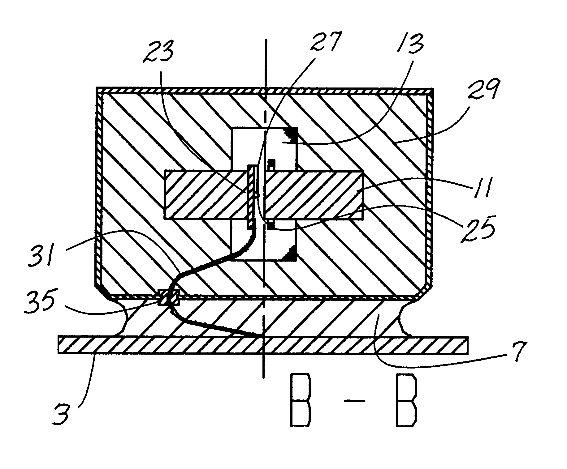
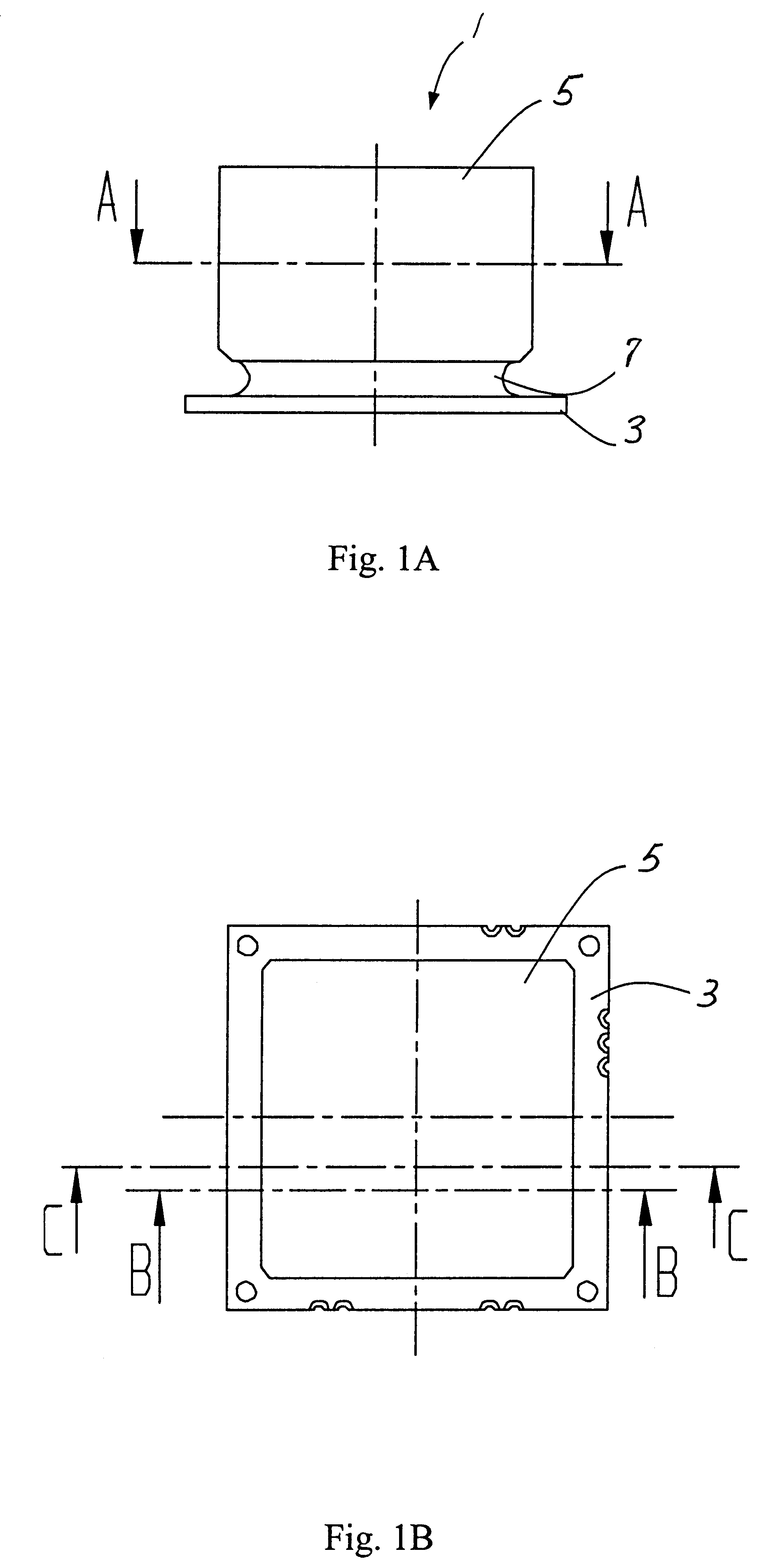
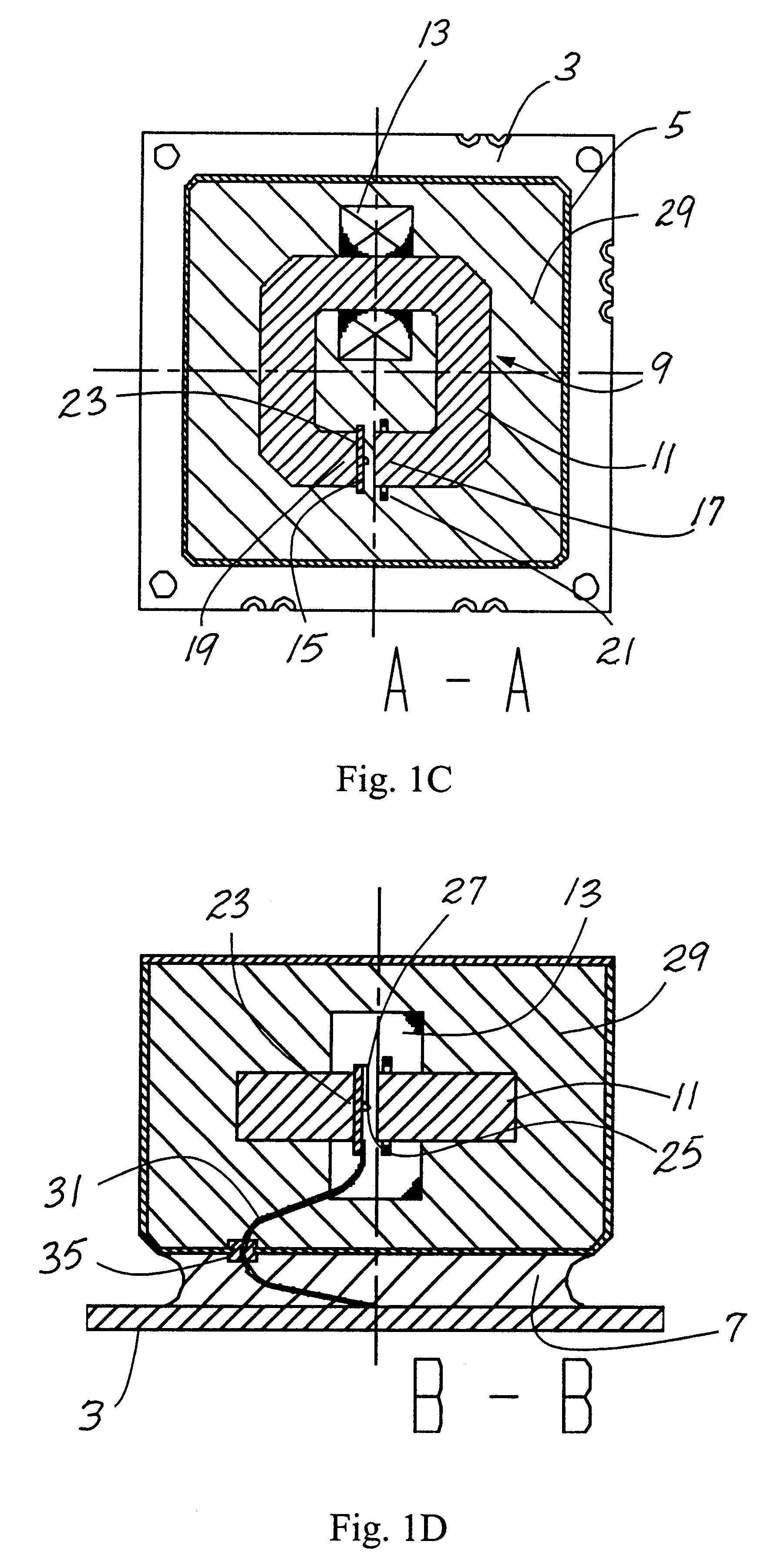
As shown in FIG. 1A the YIG oscillator 1 in one embodiment thereof comprises an interface circuit board 3, a metal enclosure 5 containing the vital oscillator parts and a first resilient means, here comprising a single resilient element, embodied as a rubber plate, 7 connecting the interface circuit board 3 with the enclosure 5. In other words, the interface circuit 3 resiliently supports, or suspends, the enclosure 5 by means of the rubber plate 7. Preferably the enclosure is of a material, such as magnetic iron, that constitutes a magnetic shield in order to protect the contents thereof from external magnetic fields.

When mounting the YIG oscillator in a device using its output frequency the interface circuit board 3 is mechanically fastened in the device, and electrically connected to the same. Preferably these are the only mechanical and electrical connections between the YIG oscillator 1 and the device.

As shown in FIGS. 1C-1E the YIG oscillator 1 further comprises a magnetic str...


PUM


Abstract

A YIG oscillator including a magnetic structure; an oscillator circuit board attached to the magnetic structure and carrying a YIG resonator positioned in an air gap of the magnetic structure; an interface circuit board including terminals for external connections, the interface circuit board supporting the magnetic structure by means of a resilient component attached to the interface circuit board; and a flexible circuit connected at one end to the oscillator circuit board and connected at the other end to the interface circuit board.

Description

This invention relates generally to YIG oscillators, and more specifically to a YIG oscillator having a low Vibration Sensitivity.TECHNICAL BACKGROUNDYIG oscillators are a favored form of fundamental electromagnetic energy generators at frequencies in the spectrum of about 1 GHz to about 100 GHz. A YIG oscillator is an oscillator comprising an yttrium iron garnet crystal, which when placed in saturating magnetic field oscillates to generate electromagnetic energy at frequencies related to the strength of the magnetic field. More particularly, the output of a YIG oscillator is linearly dependent on the magnetic flux density in an air gap of a magnetic structure where the YIG crystal is positioned. The magnetic flux density, in turn, is inversely proportional to the length of the air gap, provided that the rest of the parameters of the magnetic circuit are constant.For example, a 10 GHz YIG oscillator having an air gap length of 1 mm will exhibit a 1 kHz frequency deviation for an air...

Claims


Application Information

Patent Timeline
Patent Type & Authority Patents(United States)
IPC IPC(8): H03B5/18
CPCH03B5/18
Inventor ANDERSSON, RONNY
Owner IMA AB SIVERS
Learn More