Lighting device with integrated lens heat sink
a technology of heat sink and lighting device, which is applied in the direction of lighting support device, lighting and heating apparatus, instruments, etc., can solve the problem of large thermal gradient of light exit elemen
- Summary
- Abstract
- Description
- Claims
- Application Information
AI Technical Summary
Benefits of technology
Problems solved by technology
Method used
Image

Examples
Embodiment Construction
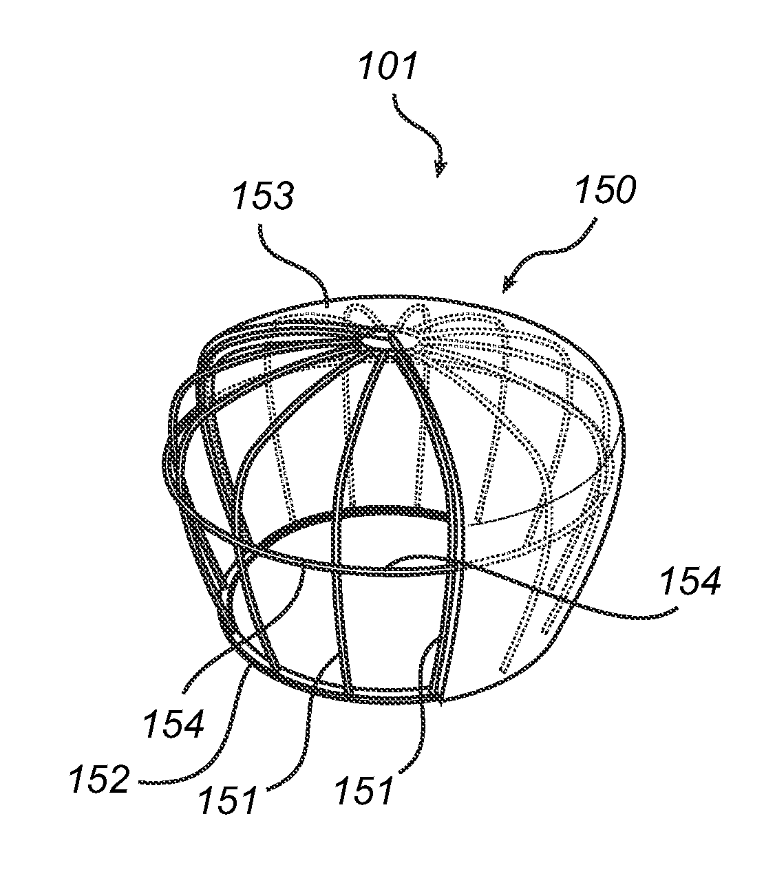
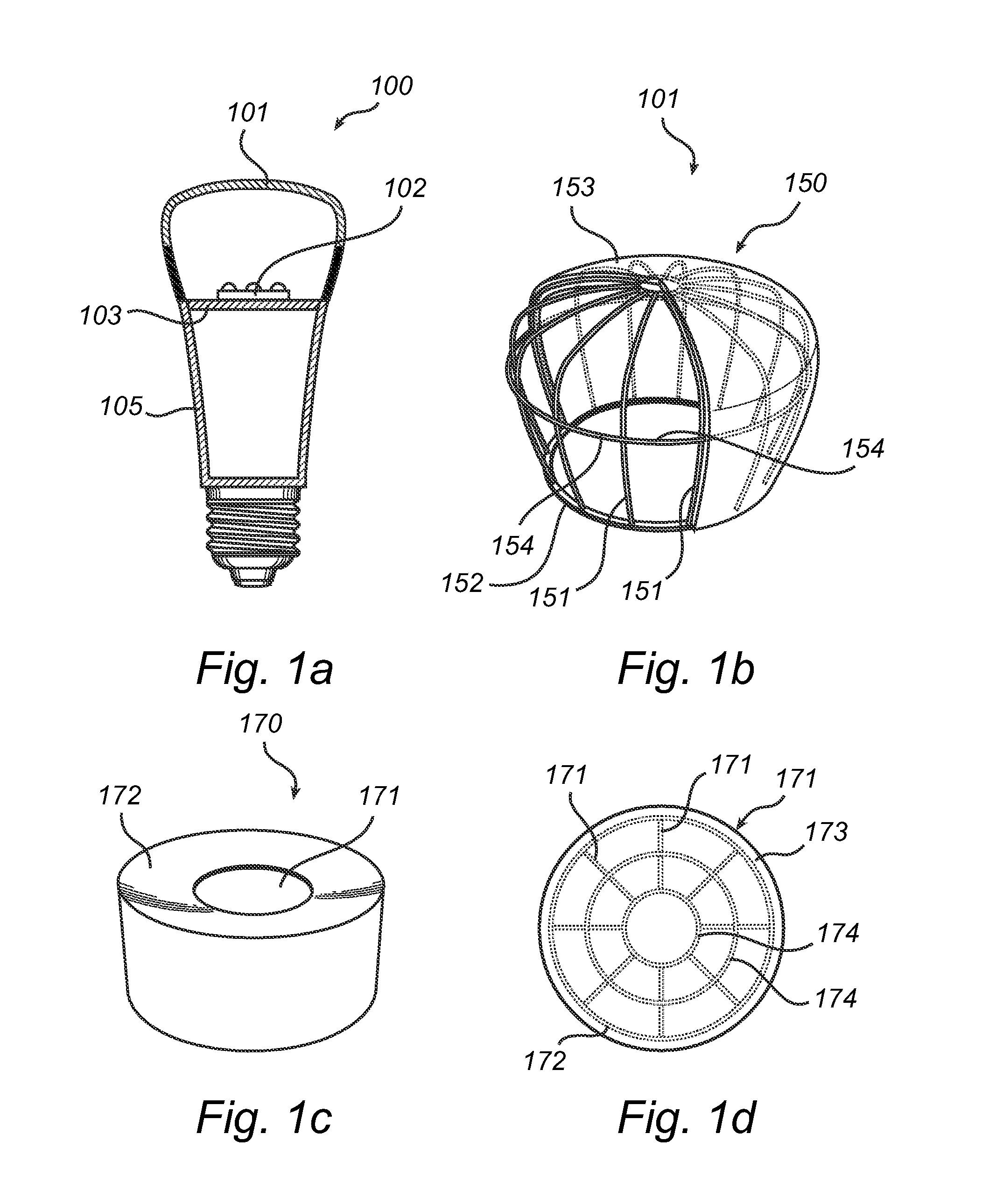
[0032]An embodiment of a lighting device according to the present inventive concept is now described with reference to FIG. 1a). The shown lighting device is here a retrofit LED based lamp 100 comprising LED-based light sources 102 arranged on a substrate 103 which is thermally connected to a heat sink, here in the form of a lamp base 105. The LED lamp 100 is further provided with drive circuitry arranged on the substrate and / or in the lamp base (not shown). A bulb envelope 101 constitutes a light exit element for the LED based lamp 100. According to embodiments, the LED lamp may further comprise control circuits to control the light output and / or to provide thermal management of LED lamp as will be described herein under.
[0033]According to the present inventive concept, the light exit element of a lighting device, such as the retrofit LED lamp 100 described with reference to FIG. 1a), is provided with a heat conducting structure arranged for distributing heat generated by the LED-b...
PUM
 Abstract
Description
Claims
Application Information
 - R&D
- Intellectual Property
- Life Sciences
- Materials
- Tech Scout
- Unparalleled Data Quality
- Higher Quality Content
- 60% Fewer Hallucinations
Browse by: Latest US Patents, China's latest patents, Technical Efficacy Thesaurus, Application Domain, Technology Topic, Popular Technical Reports.
© 2025 PatSnap. All rights reserved.Legal|Privacy policy|Modern Slavery Act Transparency Statement|Sitemap|About US| Contact US: help@patsnap.com