
Material for a dental prosthesis, method and device for determining the shape of a remaining tooth area to be provided with a dental prosthesis, method and arrangement for producing a dental prosthesis and use of the arrangement

a dental prosthesis and material technology, applied in dental prosthetics, dental preparations, tooth crowns, etc., can solve problems such as poor thermal conductivity

Inactive Publication Date: 2001-09-11
STRAUMANN HLDG AG +2
View PDF13 Cites 149 Cited by
  • Summary
  • Abstract
  • Description
  • Claims
  • Application Information

AI Technical Summary

Benefits of technology

It is therefore also the object of the invention to provide a method and a device for executing the method, which makes possible the determination of the shape of duplicates of remaining tooth areas to be provided with dental prostheses, while avoiding the above described disadvantages.
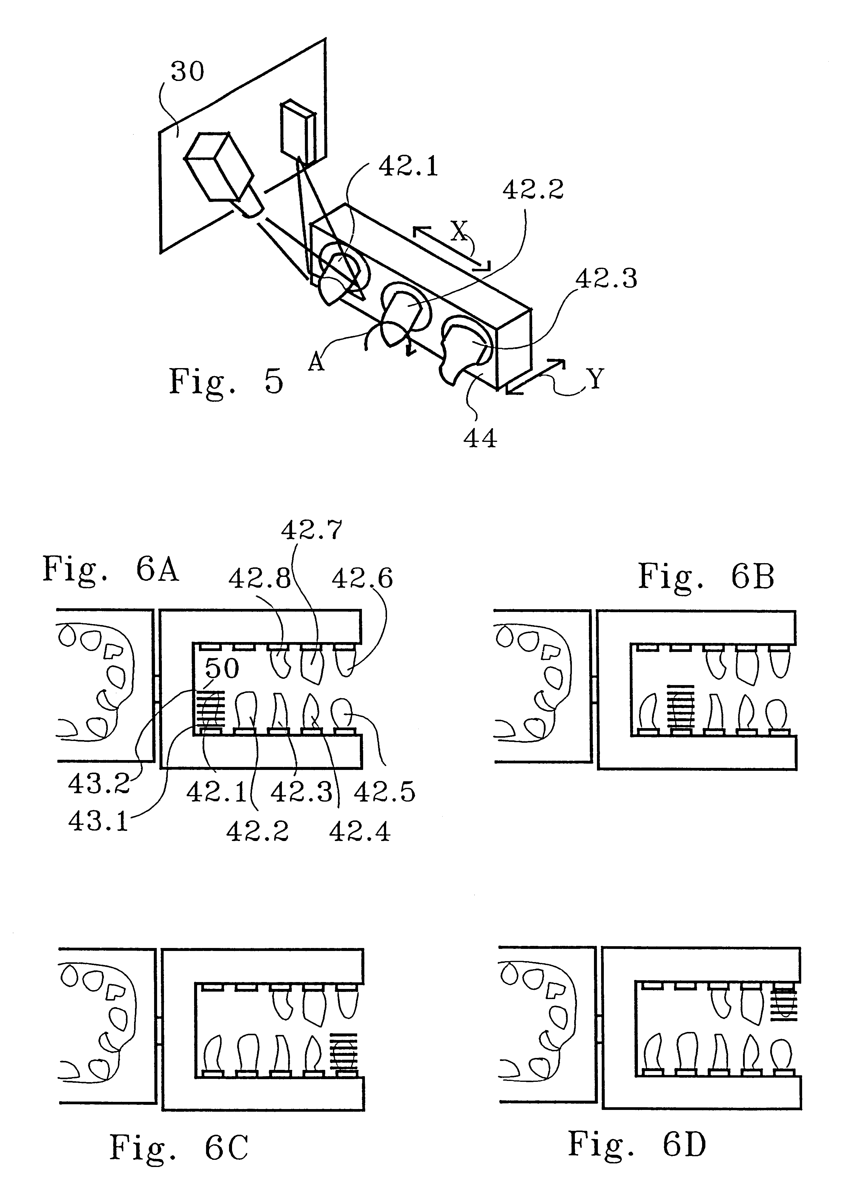
With already known methods, the production of the dental prosthesis is sometimes performed by direct copying in the manner of copy-milling, which corresponds to an analogous linkage. To this end it is not absolutely necessary to digitize the data defining the shape of the dental prosthesis to be produced. Even if the shape of the remaining tooth area to be determined is very simple, or if it is necessary to accept certain inaccuracies, so that therefore the determination of the shape takes place only by a single relative position of the duplicate, or respectively the duplicate sections, in respect to the sensor, it is not absolutely necessary to store the data characterizing the determined shapes in the form of digital values. However, it is generally unavoidable for determining the exact shape of the remaining tooth area to place the duplicate sections and the entire duplicate successively into several relative arrangements in respect to the sensor, so that the shapes can be detected by the sensor at different angles. In this case the determined data must be stored as digital data, so that subsequently the different data of the individual duplicate sections, as well as the different data of the duplicate, can be combined in a so-called three-dimensional matching process, by means of which a precise image of the remaining tooth area is obtained in a digital representation. Therefore it is necessary to digitize the determined data, so that they become suitable for processing in an electronic data processing device. The electronic data processing device permits the accumulation, or respectively the storage, of the data of several consecutively performed partial determinations, for example from several angles, and thereafter a 3D combination of the data of the entire duplicate with the data of the duplicate sections, so that the determination of the shape of the remaining tooth area as a whole can be performed with greatly increased accuracy. Digitizing the data is also advantageous in cases in which 3D-matching is not required in order to bring the data into a form in which they can be processed in a simple manner by means of an EDP installation. In addition, digitizing the data makes it possible to store them in a memory unit for later use.
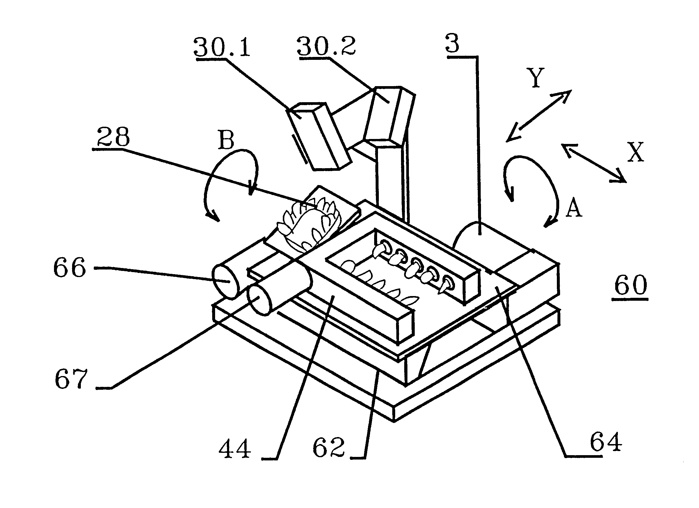
It is required for the determination of accurate data, that the sensor unit on the one hand, and on the other the duplicate sections as well as preferably the duplicate itself, can be moved relative to each other. It has been shown to be advantageous to use a sensor device which is fixed in place inside the device, and a movable duplicate clamping device as well as a movable section clamping device. To this end, the duplicate clamping device and the section clamping device are arranged individually or together on a table. This table can be supported by means of two orthogonal guides, so that it can be displaced along these in an orthogonal direction by means of a motor drive. In this way it is possible to determine the shapes of the duplicate and of the duplicate section in parallel level assemblies. The table can also be designed as a revolving plate, on which the duplicate sections and, if desired the duplicate, are arranged on a circle, wherein the revolving plate itself can be supported on a linear guide. It is also possible to either clamp the duplicate sections with their longitudinal axes, which of course are not exactly defined geometrically, approximately vertically in relation to the table, or obliquely in relation to the table, and possibly rotatable around their longitudinal axes.
It is also an object of the invention to improve the conventional methods and the devices for executing these methods in such a way, that the production of the dental prostheses can be performed faster, more accurately, and in particular independently of the mechanical skills of a dentist or dental technician, and to disclose a use of the novel arrangement.
The novel arrangement comprises a shape determination device and a machining device, or respectively other suitable production devices, for the actual production of the dental prosthesis, and an EDP installation. The EDP installation couples the shape determination device with the machining device, and also includes the memory unit for the results of the shape determination device, and the control unit for controlling the production device. The EDP installation thus not only takes on the connection of the sensor device with the machining device, but also the function of the control device of the shape determination device as well as the function of the control unit for the machining device. Thus, in this novel combination of three serial modules consisting of the shape determination device, EDP installation and machining device, a concentration of all control and monitoring functions takes place in the EDP installation, so that the shape determination device and the machining device need not have individual EDP units. This is advantageous both for the production and the maintenance of the entire arrangement and makes it possible to centrally control and monitor the entire production of the dental prosthesis.
Preferably the EDP installation of the novel arrangement includes an input unit, generally in the form of a keyboard with a mouse or a track ball. The input unit is used in particular for inputting information prior to and during the shape determination and the actual production of the dental prosthesis, and also makes it possible to intervene in a running operation, or respectively to correct previous information, which was obtained simultaneously or in another way, for example in the form of diskettes or CDs.

Problems solved by technology

In addition, it is a poor thermal conductor, so that complaints by the patient arising from thermal conduction do practically not arise.
This occurs, because the glass fibers are molded in an unaligned manner into the plastic.

Method used


Image

  • Material for a dental prosthesis, method and device for determining the shape of a remaining tooth area to be provided with a dental prosthesis, method and arrangement for producing a dental prosthesis and use of the arrangement
  • Material for a dental prosthesis, method and device for determining the shape of a remaining tooth area to be provided with a dental prosthesis, method and arrangement for producing a dental prosthesis and use of the arrangement
  • Material for a dental prosthesis, method and device for determining the shape of a remaining tooth area to be provided with a dental prosthesis, method and arrangement for producing a dental prosthesis and use of the arrangement

Examples


Embodiment Construction

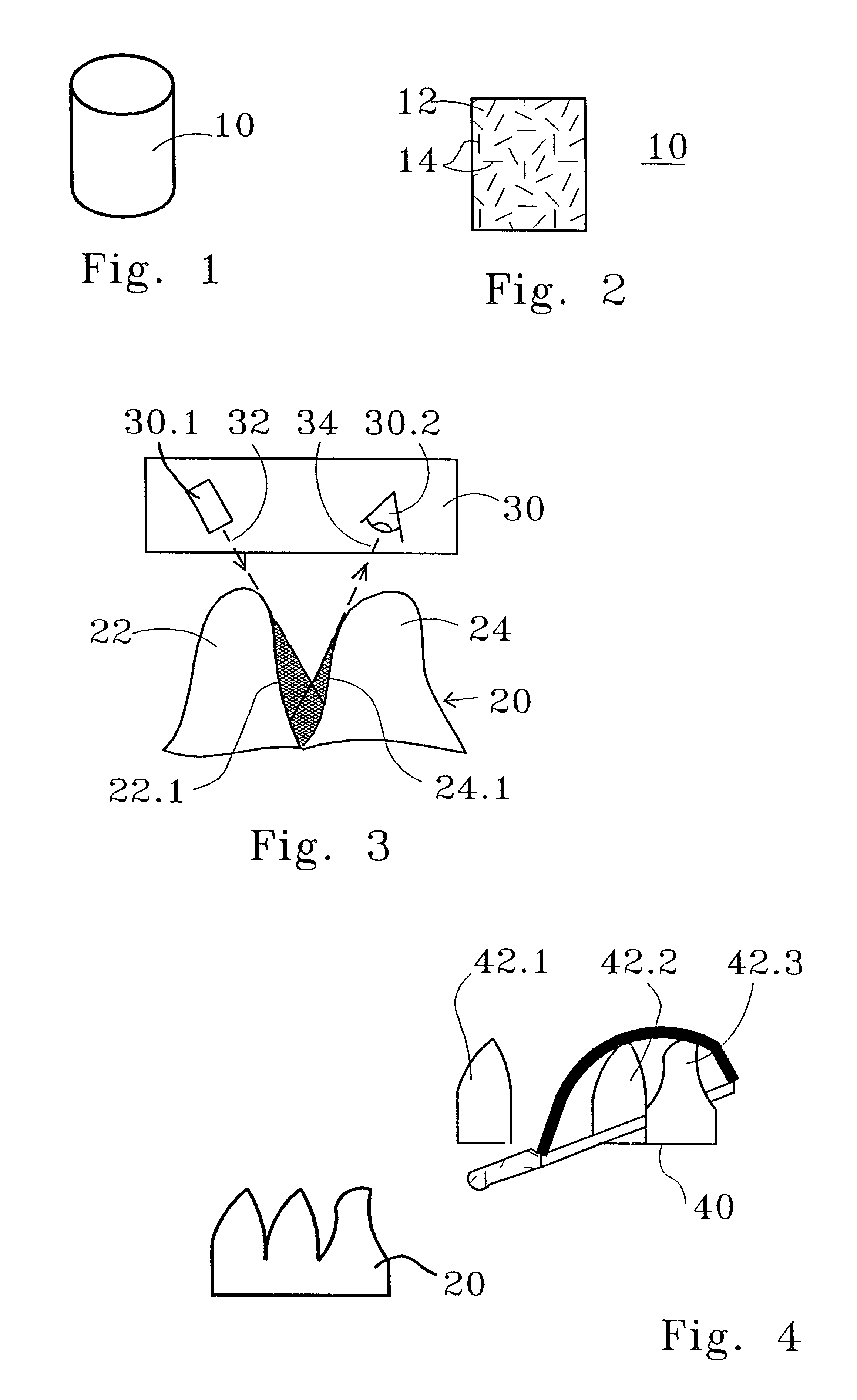
FIG. 1 shows a blank 10 made of the material in accordance with the invention, from which a dental prosthesis can be fashioned by means of machining. As represented in FIG. 1, the blank 10 can be cast with appropriate process additions as a rod or a block in the approximate size of a dental prosthesis, or in larger sizes for several dental prostheses. Blanks of the approximately size of dental prostheses can be further processed directly.

The blank 10 represented in FIG. 1 has the shape of a cylinder. However, the blanks can also be shaped differently, for example as dice, cubes, parallelipeds, suitable prisms, or possibly cones or pyramids, or respectively truncated cones or pyramids. It is only important that the dental prostheses to be produced are contained in them as far as shape and volume are concerned, and that they can be clamped in a suitable manner in the course of the production process.

The blank 10 consists of a suitable plastic material 12, which is reinforced by sectio...


PUM

PropertyMeasurementUnit
lengthaaaaaaaaaa
lengthaaaaaaaaaa
lengthaaaaaaaaaa

Abstract

Material for a dental prosthesis consisting of fiber glass reinforced plastic. The material is used to produce a blank by means of a special injection-molding process, which can be worked by means of a machining process. A method and a device for determining the shape of a duplicate of a remaining tooth area to be provided with a dental prosthesis. The shape of the duplicate is determined, as is the shape of duplicate sections into which the duplicate has been divided, the determined data are stored and combined. A method and arrangement for producing a dental prosthesis. The shape of a duplicate (42) of a remaining tooth area to be provided with the dental prosthesis is determined by means of a shape determination device (110), the determined data are stored in the form of digital data (DD), and the dental prosthesis (143) is produced in a production machine (114), which is controlled by means of production data (FD). The shape determination device (110) and the production machine (114) are coupled by means of an EDP installation (118), which contains a memory unit for storing the digital data (DD) and performs the calculation of the production data (FD).

Description

TECHNICAL FIELD OF THE INVENTIONThe invention relates to a material for a dental prosthesis made of plastic reinforced with glass fibers.BACKGROUND OF THE INVENTIONFor a long time, dental prostheses have been produced, depending on their use, as inlays, onlays or bridges and, depending on the expense justified in the individual case, from an amalgam, gold or porcelain. When using an amalgam, shaping is performed in situ, i.e. in the mouth of the patient, in that the moldable amalagam material is placed in the not yet hardened state into the cavities to be filled. Some build-up of material outside the cavity is also possible, wherein the shaping takes place either in the form of molding the pliable amalagam, or by means of grinding tools for the hardened amalagam. When using gold or porcelain, shaping is performed by the dental technician, generally in accordance with a cast, or respectively duplicate, of the dental prosthesis to be produced, which was previously made in the mouth of...

Claims


Application Information

Patent Timeline
Patent Type & Authority Patents(United States)
IPC IPC(8): A61C13/00A61K6/087A61K6/02A61K6/027A61C9/00A61C13/08A61C13/087A61C13/14A61K6/884A61K6/891
CPCA61C13/0003A61C13/0004A61K6/0276A61C9/0053A61K6/087C08L77/00A61C5/77A61K6/836A61K6/891
Inventor GUIOT, JEAN-BERNARDTRABER, TONYEFRONI, ERAN
Owner STRAUMANN HLDG AG
Learn More