
Diagnostic device and method

a diagnostic device and a technology of a diagnostic device, applied in the direction of optical radiation measurement, fluorescence/phosphorescence, instruments, etc., can solve the problem of inability to determine the presence of an ischemic even

Inactive Publication Date: 2001-04-24
UNIV OF UTAH RES FOUND
View PDF88 Cites 165 Cited by
  • Summary
  • Abstract
  • Description
  • Claims
  • Application Information

AI Technical Summary

Benefits of technology

Surprisingly, it has been found that by carefully constructing, selecting, and using a biosensor with a three (or more) cardiac marker system, results can be quickly obtained and reported back to the monitoring physician within, for example, two minutes.
The concentration of a cardiac marker is determined by a flexible time assay consisting of a rapid assay which measures the high concentration analyte faster than the lower concentration analytes. Such a rapid assay can be utilized because patients suffering from acute myocardial infarctions have elevated levels of the cardiac marker proteins in their blood. For such elevated levels, less reaction time is required to achieve a given precision in the assay determination.

Problems solved by technology

Thus, the time delay of the present generation of clinical diagnostics assays, including the one-half hour delay disclosed in the Jackowski patent, to determine the presence of an ischemic event is unacceptable.

Method used


Image

  • Diagnostic device and method
  • Diagnostic device and method
  • Diagnostic device and method

Examples


example i

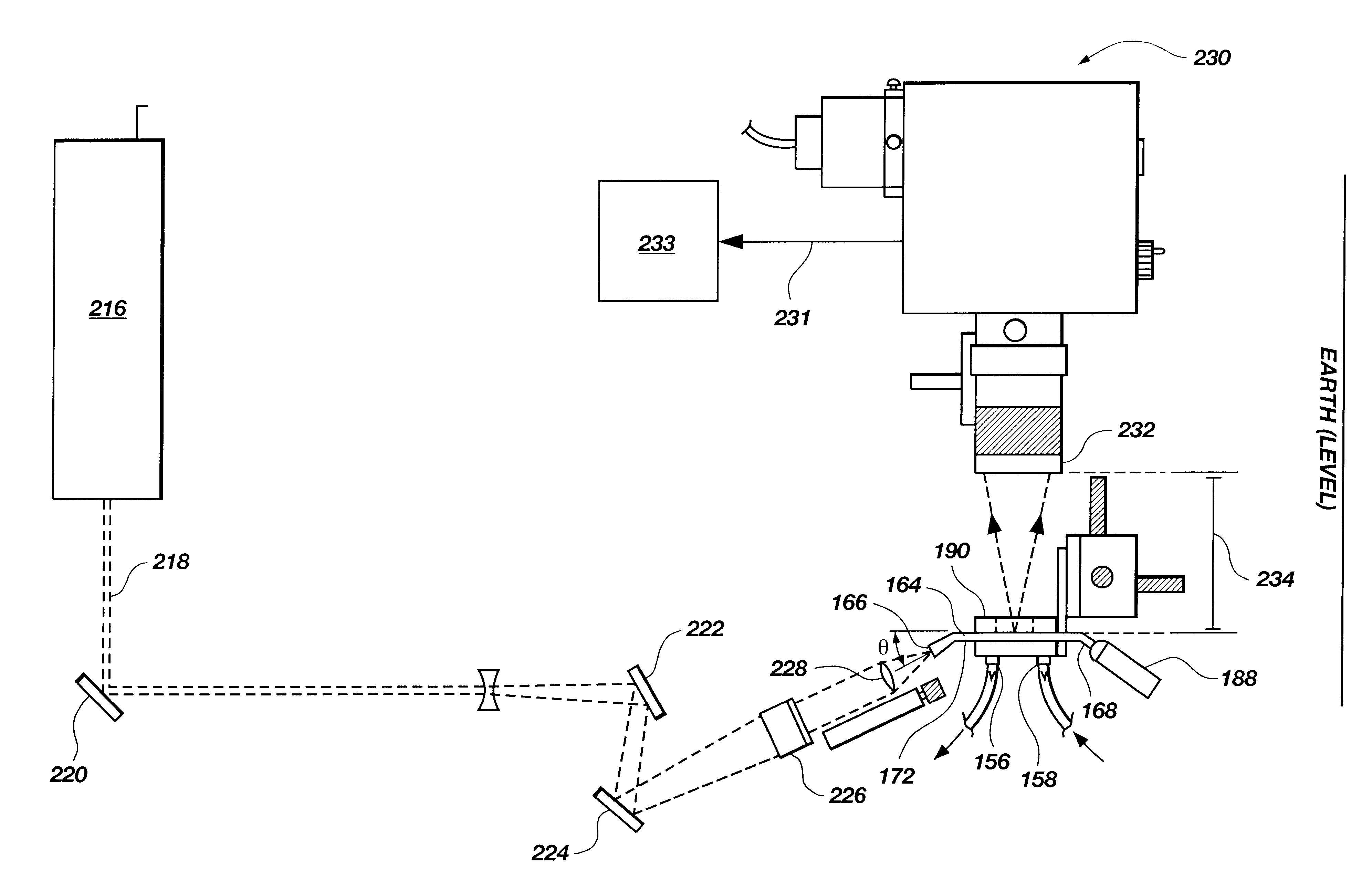
A waveguide with integrated lenses, such as that depicted in FIGS. 6 & 7, was injection molded in a clean environment from a transparent, general purpose polystyrene. The waveguide had a length of 38 mm, and a width of 25 mm. The thickness 173 of the planar surface 170 was a consistent 0.5 mm. The ridge or "shelf" 176 had a height of 1.3 mm. The front lens and rear lens had bottom edges co-planar with their respective centers of curvature. The front lens horizontal angle 262 was about 15.degree.. The rear lens horizontal angle 264 was about 19.degree.. The radii of curvature of the front and rear lenses were about 3.2 mm and 1.6 mm respectively. The mean angle of the front lens was 21.degree.. The mean angle of the rear lens was about 24.degree..

example ii

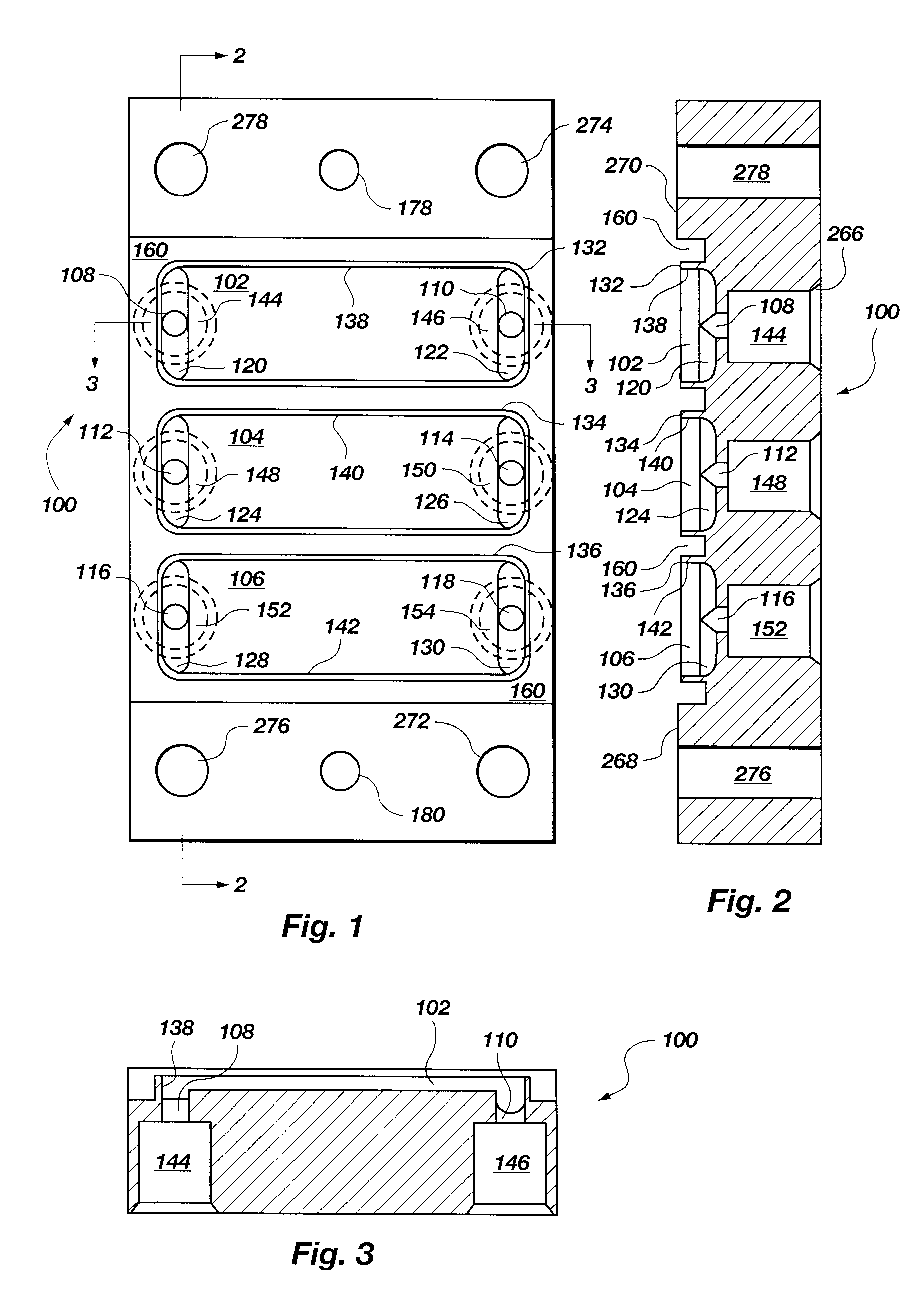
A flow cell top 100, such as that depicted in FIGS. 1-3, and 10, was made of hard black anodized 6061-T6 aluminum. It contained three reservoirs, each of which had a 0.25 mm (0.010 in.) thick wall surrounding it, a flat floor in the middle, two half-capsule shaped recesses at either end 1.6 mm (1 / 16 in.) in width, and ports 1.6 mm (1 / 16 in.) in diameter running into the center of each recess. The ports opened into a #10-32 (standard thread, not NPT) connector which ran out to the opposite face of the flow cell and was 5.1 mm (0.200 in.) deep. A 90.degree. countersink 266 (FIG. 2) was given at the surface of the port connector (a plastic barbed tubing connector screwed into the port connector and sealed on the countersink). On both sides of the array of reservoirs were two raised platforms which were referred to as lands 268, 270. Each land had three holes running through the thickness of the part. The four #31 clamping holes 272, 274, 276, 278 were formed (i.e., drilled through). Th...

example iii

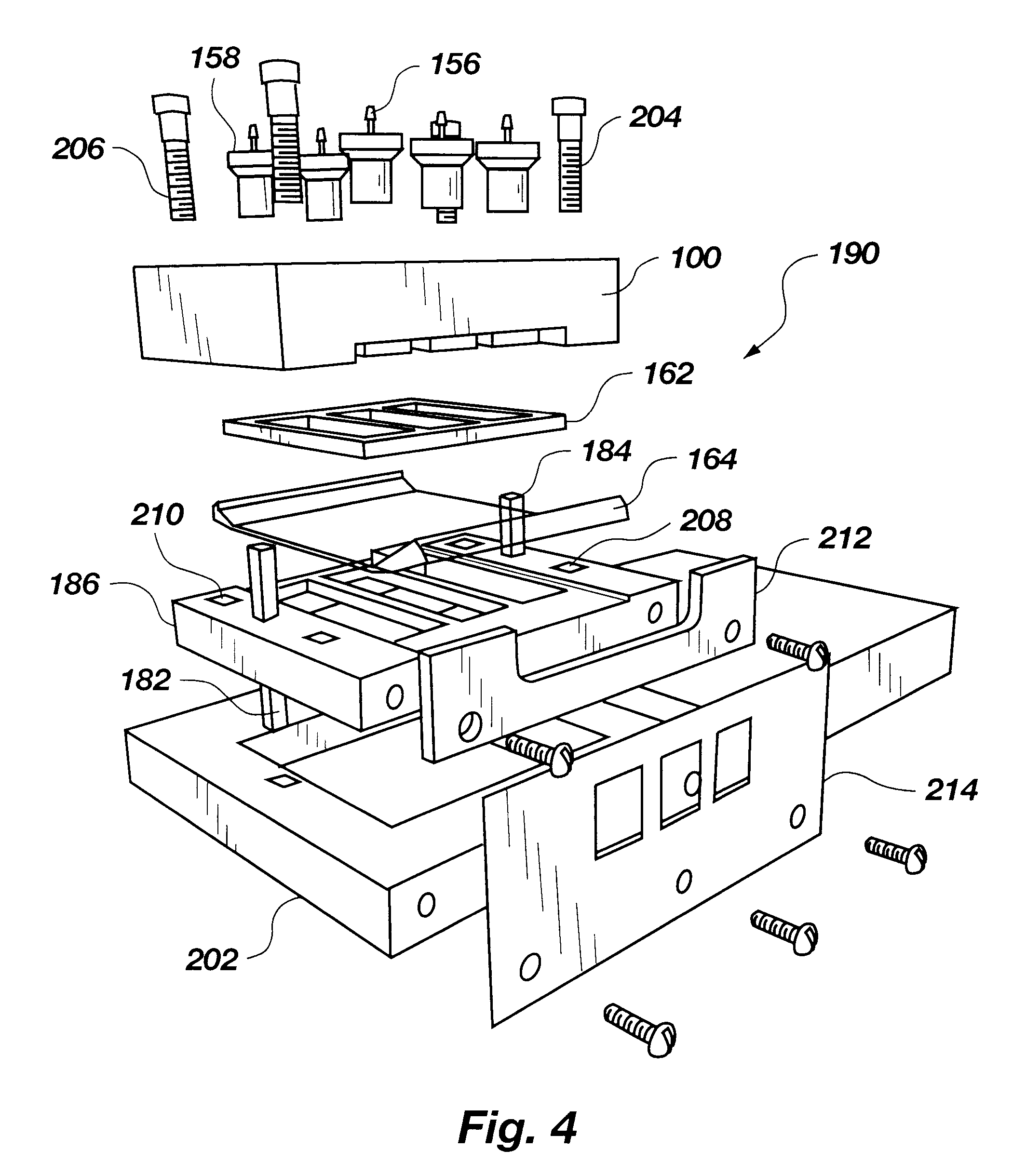
A gasket 162, such as that depicted in FIGS. 4 and 5, was made as a composite structure laminated from 1.6 mm (1 / 16 in.) silicone rubber sheeting and 0.076 mm (0.003 in.) self-adhesive FEP film (total thickness: 1.676 mm (0.066 in.) nominal). Its outer dimensions were about 25 mm (1 in.) by 25.40 mm (1.000 in.) and it had three internal openings which corresponded to the flow cell reservoirs. The gasket was produced using a waterjet cutter and was seated on the flow cell such that the FEP layer faced away from the flow cell surface.


PUM


Abstract

A method and apparatus of diagnosing a cardiac disease state in as little as two minutes involving the utilization of an evanescent wave assay system in conjunction with a data acquisition and analysis procedure that monitors the precision of assay results in real time (i.e., while data is being acquired). The method includes diagnosing a disease state using a diagnostic procedure (e.g., an immunoassay) wherein the testing device informs the person conducting the test of the results of the test as soon as reliable test data is obtained (generally, <5% variation in the reaction rate of the assay). After which point, the diagnostic procedure may be terminated.

Description

The invention generally relates to diagnostic devices and, more particularly, to a point-of-care diagnostic device useful in the quick differential diagnosis of a myocardial infarction or similar event in a subject.Various cardiac markers are used in the diagnosis of cardiac function and disease. Among these markers is troponin. Troponin is a protein complex which regulates the contraction of striated muscle. The troponin protein complex includes three distinct proteins. The first is troponin I which is an inhibitory sub-unit. The second is troponin C which is a calcium binding sub-unit. The third is troponin T, a sub-unit which attaches the troponin protein complex to tropomyosin on the thin filament of the striated muscle.Troponin I is believed to exist in three isoforms, one of which exists in cardiac muscle, while the other two exist in skeletal muscle. The skeletal muscle isoforms are nearly identical, and have molecular weights of about 19,800 Daltons. Structurally, the cardia...

Claims


Application Information

Patent Timeline
IPC IPC(8): G01N33/68G01N33/543G01N21/05G01N33/48G01N33/483G01N21/64
CPCG01N33/54373G01N33/68G01N2333/4712
Inventor HERRON, JAMES N.CHRISTENSEN, DOUGLAS A.DURTSCHI, JACOB D.
Owner UNIV OF UTAH RES FOUND
Learn More