
High intensity discharge lamp ballast

a high-intensity discharge and lamp ballast technology, applied in the direction of sustainable buildings, efficient power electronics conversion, electric variable regulation, etc., can solve the problems of catastrophic failure of the arc tube, limiting the practical length of the wiring between the igniter circuit and the lamp, alarming and dangerous problems

Inactive Publication Date: 2001-02-13
GREENWOOD SIMON RICHARD +1
View PDF39 Cites 55 Cited by
  • Summary
  • Abstract
  • Description
  • Claims
  • Application Information

AI Technical Summary

Benefits of technology

By operating in two modes, respectively at high and low frequency, the invention overcomes many of the problems associated with prior art HID lamp ballasts. The first, high frequency mode is operated at typically greater than 20 kHz while the lamp is cold and uses resonance to cause the lamp to strike. Once the lamp has warmed up sufficiently for thermionic emission from the lamp electrodes, the second mode of operation may be employed at typically less than 1 kHz and the lamp arc will be maintained. Because resonance in the first mode of operation is used to provide sufficient voltage to strike the lamp, there is no requirement for a separate igniter circuit and consequently the expense of components such as the Sidac can be avoided.
Preferably, a first return capacitor is connected between the second lamp terminal and the positive high voltage rail and a second return capacitor is connected between the second lamp terminal and the negative high voltage rail. Because the lamp voltage is boosted by resonance in the first mode of operation and because a comparatively low lamp voltage is required to maintain the arc in the second mode of operation, it is possible to run the lamp according to the invention using only half the voltage from the split high voltage supply. Thus a full transistor bridge circuit is not necessary and return capacitors may replace two of the transistors, with consequent cost savings.

Problems solved by technology

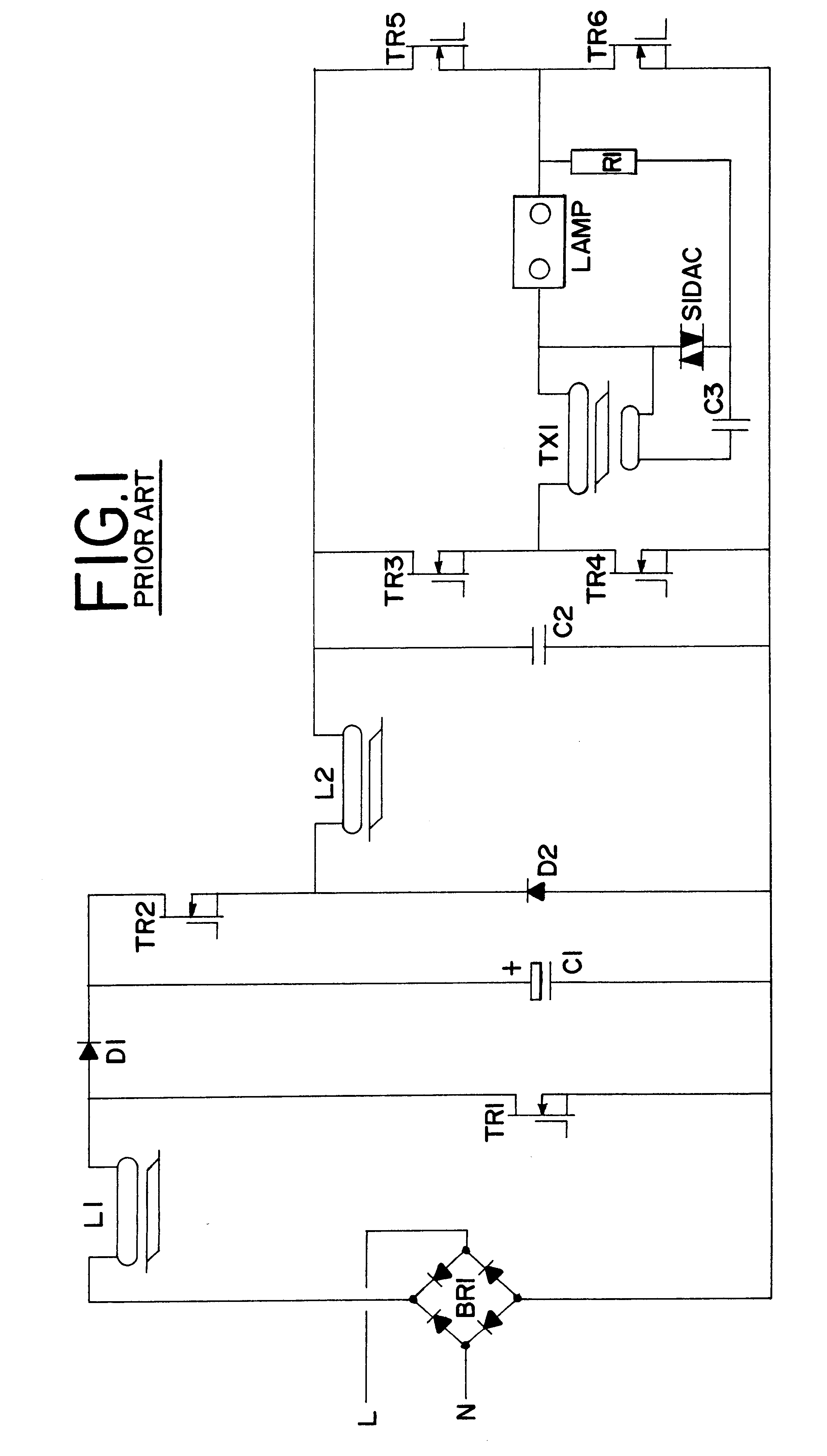
Because of the high rate of rise of voltage, the capacitance and inductance of the wiring to the lamp act to attenuate the high voltage ignition pulse to the lamp, so limiting the practical length of the wiring between the igniter circuit and the lamp.
Attempts have been made to design high frequency electronic ballasts for HID lamps with some level of success but these are fraught with problems due mainly to the predisposition of many HID lamps to acoustic arc resonance when operated at frequencies substantially above line frequency.
It is in some cases possible to design high frequency ballasts specifically for one type and size of HID tube if the operating frequency of the ballast is chosen carefully but if the gas pressure in the tube changes substantially during the life of the tube the resonance characteristics will also change and could cause catastrophic failure of the arc tube.
This will be at best alarming and could be dangerous if the arc tube fragments are not sufficiently contained within the lamp fitting (luminaire).

Method used


Image

  • High intensity discharge lamp ballast
  • High intensity discharge lamp ballast
  • High intensity discharge lamp ballast

Examples


Embodiment Construction

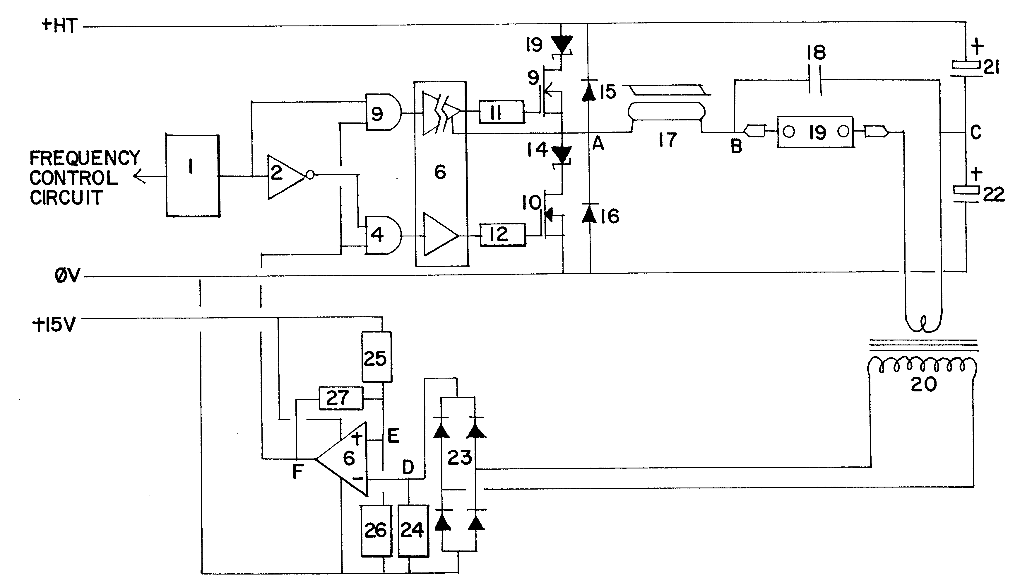
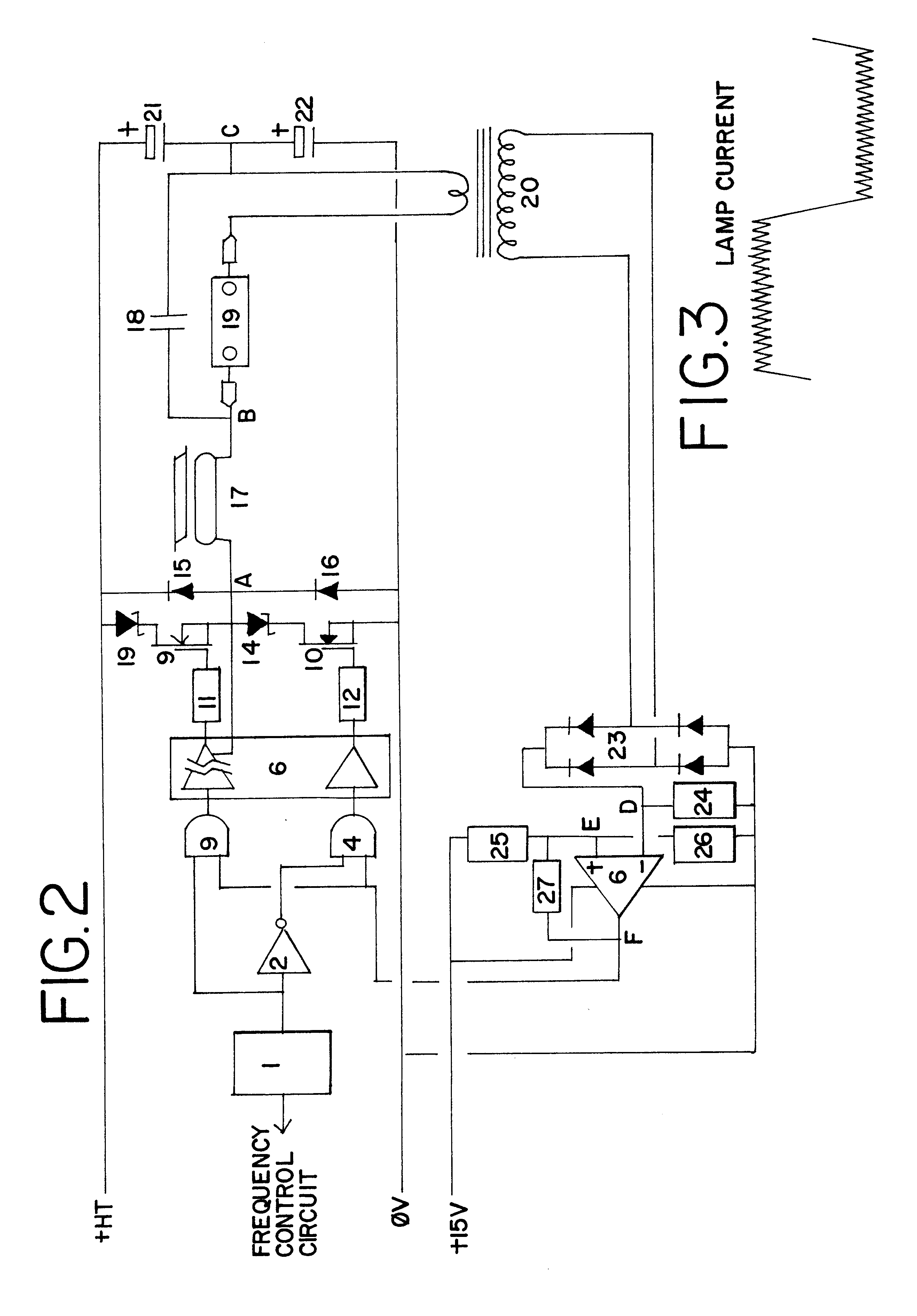
FIG. 2 shows a first embodiment of the invention in which the operation of the circuit is characterised by two discrete modes.

A frequency control circuit (not shown) controls the output frequency of oscillator 1, which outputs a square wave. The output of the oscillator 1 is split, one half being passed through an inverter 2, to create two complementary outputs in anti-phase with each other. These anti-phase outputs are connected to the inputs of two dual input AND gates 3 and 4, the other inputs of the two AND gates being connected to the output of a voltage comparator 5. The outputs of the two AND gates 3, 4 are connected to a MOS gate driver IC 6, which drives a pair of MOSFETs 9, 10 via gate drive resistors 11, 12. The MOS gate driver IC 6 is provided with means of isolation which allows the gate of the "high side" MOSFET 9 to be driven at a voltage referenced to the source connection of the MOSFET. Each MOSFET 9, 10 is provided with a series connected Schottky diode 13, 14 and ...


PUM


Abstract

A means of ballasting for high intensity discharge (HID) lamps, wherein the necessary lamp striking voltage, warm-up current and steady state running current may all be controlled using only two power switching transistors 9,10 operating in two discrete modes. A further feature provides a means of lamp power control over a range of lamp voltages such that the lamp power input remains substantially constant throughout the ageing of the lamp 19. The use of this means of ballasting HID lamps can offer major cost benefits, lower circuit complexity, longer lamp life and colour maintenance and increased flexibility of the wiring installation and lamp position relative to the ballasting and striking means.

Description

This application claims foreign priority under 35 U.S.C. .sctn.119(a)-(d) or 356(b) of Great Britain Applications Nos. 9812703.8 (pending) and 9904913.2 (pending), filed Jun. 13, 1998 and Mar. 3, 1999, respectively.DESCRIPTION1. Technical FieldThis invention relates to a power control circuit which is particularly, though not exclusively, suited to the ballasting of low and high pressure sodium, mercury arc and metal halide discharge lamps (high intensity discharge lamps or HID lamps). Typically such systems can be used for highway lighting, architectural floodlighting, warehouse and industrial lighting etc.2. Background of the InventionTraditionally, ballasting for HID lamps is by use of inductors or chokes capable of controlling the lamp current through the impedance they present in series with the mains supply voltage. With some types of HID lamp a high striking voltage, typically 4-5 kV, is required to ionize the gas filling the tube and initiate the arc.In prior art systems for...

Claims


Application Information

Patent Timeline
IPC IPC(8): H05B41/38H05B41/28H02M3/158H02M3/04H05B41/288H05B41/39H05B41/392H05B41/292
CPCH02M3/158H02M3/1582H05B41/2883H05B41/2886H05B41/2888H05B41/2925H05B41/382H05B41/388H05B41/392H02M2001/0045Y02B20/204Y02B20/208Y02B70/1425Y10S315/07Y10S315/02H02M1/0045Y02B20/00Y02B70/10
Inventor GREENWOOD, SIMON RICHARDSOAR, STEPHEN
Owner GREENWOOD SIMON RICHARD
Learn More