
Silicon carbide wafer and semiconductor device applied the same

a technology of silicon carbide and semiconductors, applied in semiconductor/solid-state device testing/measurement, instruments, crystal growth process, etc., can solve the problems of difficult to secure constant properties of silicon carbide ingots and wafers, and achieve the effect of improving device characteristics and yield

Pending Publication Date: 2022-10-06
SENIC INC
View PDF0 Cites 0 Cited by
  • Summary
  • Abstract
  • Description
  • Claims
  • Application Information

AI Technical Summary

Benefits of technology

The patent aims to provide a silicon carbide wafer with fewer defects and better crystal quality. It also aims to reduce the number of abnormal peak signals in the intensity spectrum of a silicon carbide wafer. By doing so, it can improve device characteristics and yield.

Problems solved by technology

However, current density and temperature distribution inside the crucible change depending on properties of the crucible, the process condition, and so on, such that securing constant properties of a silicon carbide ingot and a wafer is difficult.

Method used


Image

  • Silicon carbide wafer and semiconductor device applied the same
  • Silicon carbide wafer and semiconductor device applied the same
  • Silicon carbide wafer and semiconductor device applied the same

Examples


example 1

on of Silicon Carbide Wafer

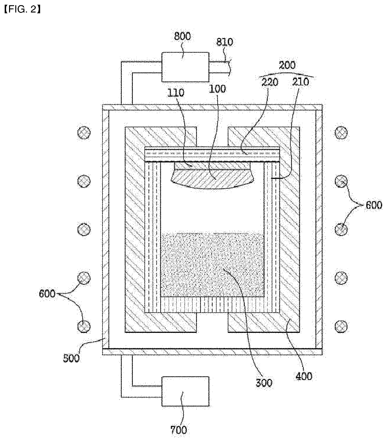
[0132]As shown in FIG. 2 as an example of an apparatus for manufacturing a silicon carbide ingot, a silicon carbide powder, which is a raw material 300, is charged in the lower portion of the inner space of the reaction vessel 200, and a silicon carbide seed crystal 110 is disposed on the upper portion. At this time, the silicon carbide seed crystal composed of 6-inch 4H-silicon carbide crystal was applied and was fixed in a conventional manner so that the C surface ((000-1) surface) was directed to the silicon carbide raw material disposed at the bottom of the inner space.

[0133]After sealing the reaction vessel 200 and surrounding the outside thereof with a heat insulating material 400, the reaction vessel was disposed within a quartz tube 500 provided with a heating coil serving as a heating means 600 on the outside. The inner space of the reaction vessel was reduced in pressure to adjust to a vacuum atmosphere, and argon gas was injected so that the inn...

example 2

on of Silicon Carbide Wafer

[0137]In Example 1, a silicon carbide wafer was prepared by changing the temperature conditions during pre-growth and growth to those of Table 1 below.

example 3

on of Silicon Carbide Wafer

[0138]In Example 1, a silicon carbide wafer was prepared by changing the temperature conditions during pre-growth and growth to those of Table 1 below.


PUM


Abstract

In a silicon carbide wafer in an embodiment, in the photoluminescence signal intensity spectrum obtained after irradiating a laser on one surface of the silicon carbide wafer, the number of peak signals having an intensity more than 1.2 times the average signal intensity of the spectrum is 1 / cm2 or less.

Description

CROSS-REFERENCE TO RELATED APPLICATIONS[0001]This application claims the benefit under 35 USC 119(a) of Korean Patent Application No. 10-2021-0041021 filed on Mar. 30, 2021 in the Korean Intellectual Property Office, the entire disclosures of which are incorporated herein by reference for all purposes.BACKGROUNDTechnical Field[0002]The present disclosure relates to a silicon carbide wafer and a semiconductor device to which the same is applied.Description of Art[0003]Silicon Carbide (SiC) is a semiconductor having a wide band gab of 2.2 eV to 3.3 eV, and the research and development for SiC as a semiconductor material have been made due to its excellent physical and chemical properties.[0004]As for methods of manufacturing a silicon carbide seed crystal, liquid phase epitaxy (LPE), chemical vapor deposition (CVD), and physical vapor transport (PVT) are known. Among them, physical vapor transport (PVT) is a method of charging a silicon carbide material inside a crucible, disposing a ...

Claims


Application Information

Patent Timeline
IPC IPC(8): H01L29/16H01L21/02
CPCH01L29/1608H01L21/02002C30B29/36C30B23/00G01N21/9505H01L21/02529H01L21/02598H01L21/0262H01L22/12C30B23/06H01L21/02008
Inventor CHOI, JUNG WOOPARK, JONG HWIKIM, JUNG-GYUSEO, JUNG DOOKU, KAP-RYEOL
Owner SENIC INC
Learn More