
Ceramic substrate and ceramic substrate manufacturing method

a ceramic substrate and ceramic technology, applied in the direction of manufacturing tools, soldering equipment, semiconductor/solid-state device details, etc., can solve the problems of deterioration of difficult to perform etching and dimple forming processes, and increase product price and product competitiveness, so as to improve electrical characteristics such as electrical conductivity and thermal resistance, the effect of improving strength and bonding strength

Pending Publication Date: 2022-10-06
AMOSENSE
View PDF3 Cites 0 Cited by
  • Summary
  • Abstract
  • Description
  • Claims
  • Application Information

AI Technical Summary

Benefits of technology

The ceramic substrate and manufacturing method described in this patent have improved electrical and thermal properties, as well as increased crack and separation resistance compared to existing methods. Additionally, the substrate can maintain strong strength and bonding strength, and can be used for fine patterns. The manufacturing method also reduces post-processing costs and improves long-term reliability of the substrate. Overall, this patent provides a more efficient and reliable solution for ceramic substrate manufacturing.

Problems solved by technology

Si3N4 and SiC have high strength, but are expensive, and thus, the product price increases and product competitiveness decreases.
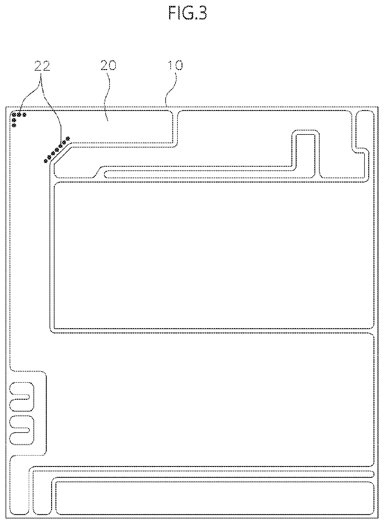
However, because the plurality of dimples 22 are formed in the dimple-type ceramic AMB substrate, an area of the metal layer 20 decreases, resulting in a deterioration of electrical characteristics such as electrical conductivity and thermal resistance.
Meanwhile, when a thickness of the metal layer 20 is greater than or equal to a certain degree according to specs, it is difficult to perform etching and dimple forming processes and there are concerns about excessive consumption of time and substrate damage.

Method used


Image

  • Ceramic substrate and ceramic substrate manufacturing method
  • Ceramic substrate and ceramic substrate manufacturing method
  • Ceramic substrate and ceramic substrate manufacturing method

Examples


Embodiment Construction

[0041]Hereinafter, the most exemplary embodiment of the present invention will be described with reference to the accompanying drawings in order to describe in detail enough that those of ordinary skill in the art may easily implement the technical idea of the present invention. First, in adding reference numerals to the components of each drawing, it should be noted that the same components are given the same reference numerals as much as possible even though they are indicated on different drawings. In addition, in describing the present invention, when it is determined that a detailed description of a related known configuration or function may obscure the gist of the present invention, the detailed description thereof will be omitted.

[0042]Referring to FIG. 4, a ceramic substrate 100 according to an embodiment of the present invention includes a ceramic base material 120 and a metal layer 140.

[0043]The ceramic base material 120 is formed of a ceramic material selected from zirco...


PUM

PropertyMeasurementUnit
angleaaaaaaaaaa
angleaaaaaaaaaa
thicknessaaaaaaaaaa

Abstract

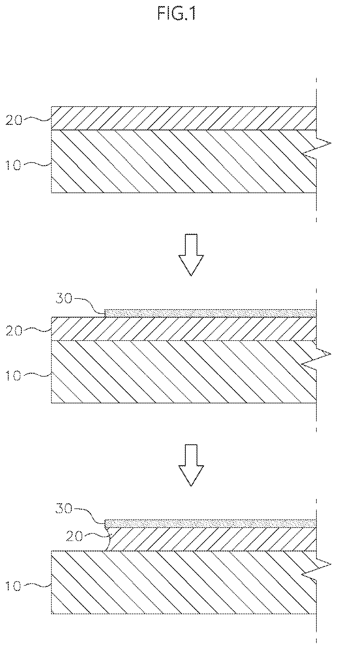
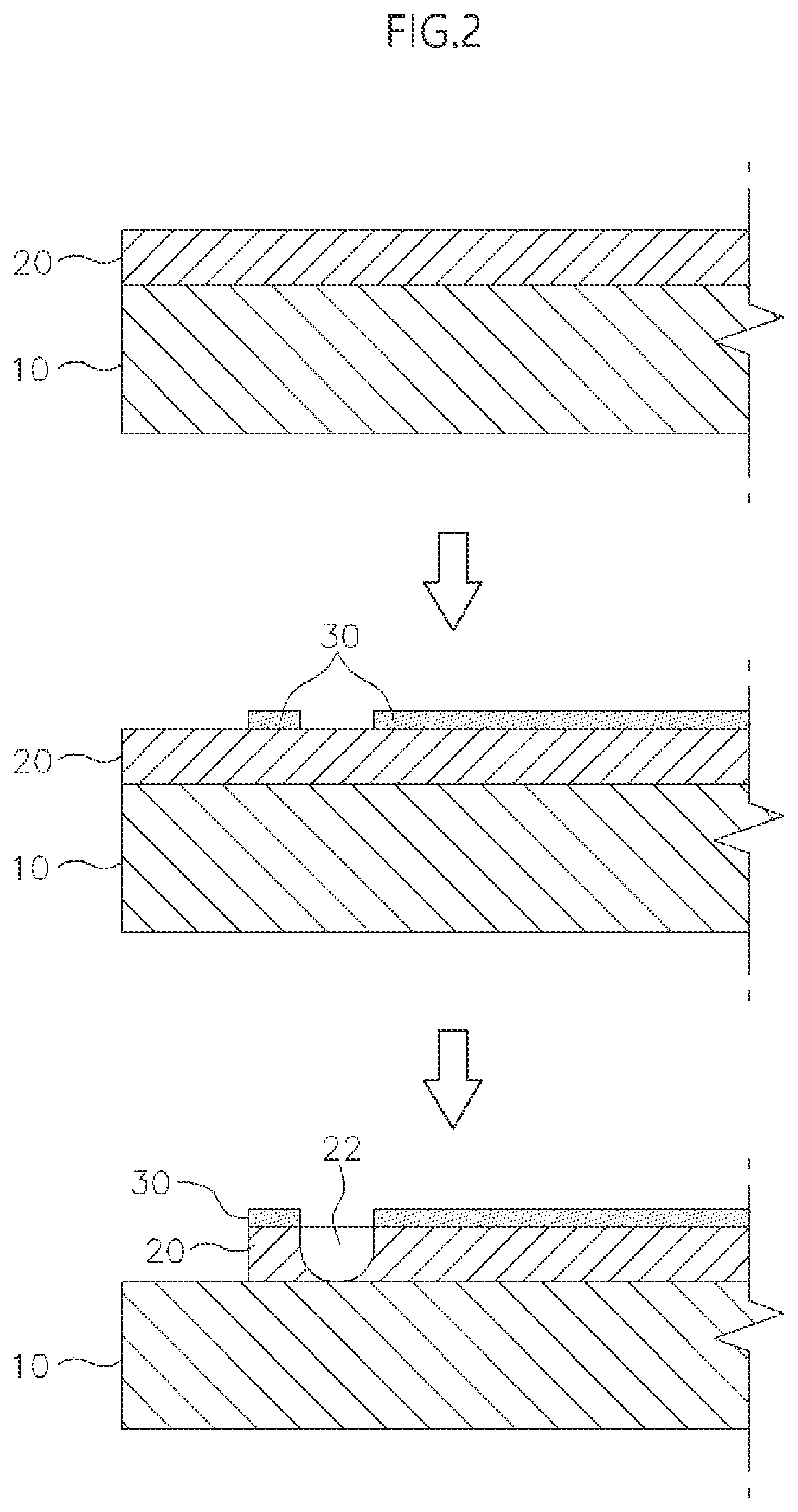
The present invention is a method of manufacturing a ceramic substrate, the method including forming a mask on one surface of a metal layer, forming an inclined protrusion by etching the metal layer exposed by the mask, and bonding the metal layer on which the inclined protrusion is formed to a ceramic base material, and according to the present invention, the inclined protrusion is formed on an outer perimeter of the metal layer bonded to the ceramic base material to increase a bonding strength between the ceramic base material and the metal layer and facilitate a metal layer etching process.

Description

TECHNICAL FIELD[0001]The present invention relates to a ceramic substrate and a method of manufacturing a ceramic substrate and, more specifically, to a ceramic substrate and a method of manufacturing a ceramic substrate, which strongly maintain a bonding state between a ceramic base material and a metal layer despite a sudden temperature change.BACKGROUND ART[0002]Ceramic substrate are formed by integrally attaching a metal foil such as copper foil to a ceramic base material. The ceramic substrates are produced through manufacturing processes such as active metal brazing (AMB), direct bond copper (DBC), and the like, and may be classified into a ceramic AMB substrate, a ceramic DBC substrate, and the like according to differences in manufacturing processes.[0003]Ceramic AMB substrates are manufactured by an AMB method of brazing a metal on a surface of a ceramic base material without performing metallization (or, metal wiring) on the surface of the ceramic base material.[0004]Ceram...

Claims


Application Information

Patent Timeline
Patent Type & Authority Applications(United States)
IPC IPC(8): C23F1/02B23K1/20
CPCC23F1/02B23K1/20B23K2103/52H01L21/768H01L21/48H01L23/15H01L21/02H01L21/4807H01L21/02422H01L21/76838
Inventor LEE, JI-HYUNG
Owner AMOSENSE
Learn More