
Method for recovering carbon dioxide gas and other gases

Pending Publication Date: 2022-07-28
TOKUYAMA CORP
View PDF0 Cites 0 Cited by
  • Summary
  • Abstract
  • Description
  • Claims
  • Application Information

AI Technical Summary

Benefits of technology

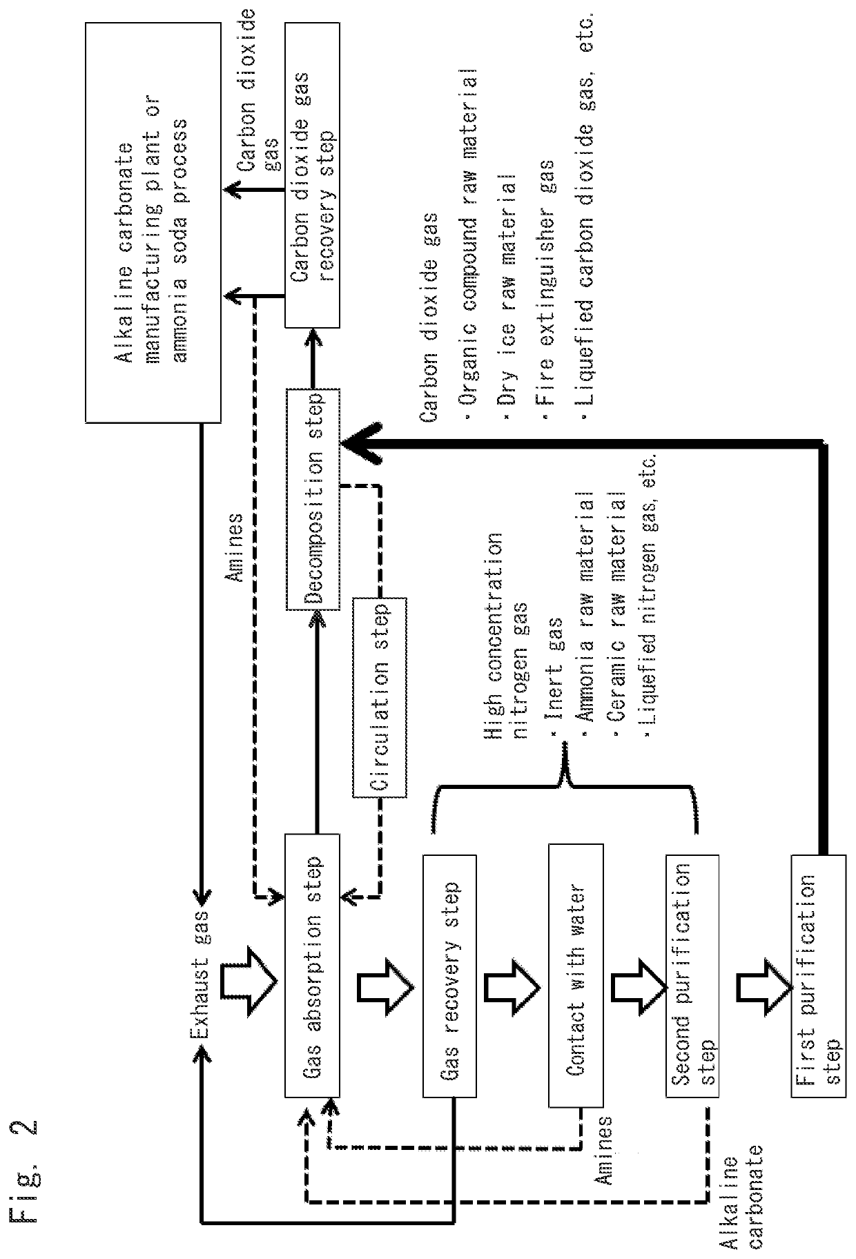
The present invention provides a method for efficiently separating high purity carbon dioxide gas from exhaust gas using an inexpensive and safe method. This can be easily incorporated into the cycle of a large-scale factory and helps prevent the emission of carbon dioxide gas to the outside of the factory. Additionally, the invention provides a combination of amines and alkaline carbonate for more efficient recovery of carbon dioxide gas. The recovered carbon dioxide gas can be utilized in various industrial applications such as alcohol production and fire extinguishing. In another aspect, the invention allows for the recovery of a gas containing nitrogen gas and oxygen gas with reduced amount of carbon dioxide gas. This is possible by using an aqueous solution containing potassium carbonate which results in an increase in the rate of carbon dioxide gas recovery.

Problems solved by technology

However, if these fuels are used at this rate, the global environment will evidently be destroyed by the excessive emission of greenhouse gases as typified by carbon dioxide gas.
However, when an absorbent made only of amines is used, an odor is generated.
Moreover, amines may necessitate complicated handling when being removed upon the recovery of carbon dioxide gas.
Such a structure sometimes requires inert gases and the like, which may decrease the efficiency of recovering carbon dioxide gas depending on the type of amines.
In order to improve the aforementioned problems, it is necessary to make a costly investment in equipment, for example.
In addition, depending on the type of amines to be used, a lot of energy may be consumed for the improvement of stability and for the separation and removal of carbon dioxide gas to be obtained depending on the concentration thereof.
However, since this method uses a steam stripping process to recover carbon dioxide gas, the resultant carbon dioxide gas is likely to contain moisture.

Method used


Image

  • Method for recovering carbon dioxide gas and other gases
  • Method for recovering carbon dioxide gas and other gases

Examples


example 1

Gas Absorption Step:

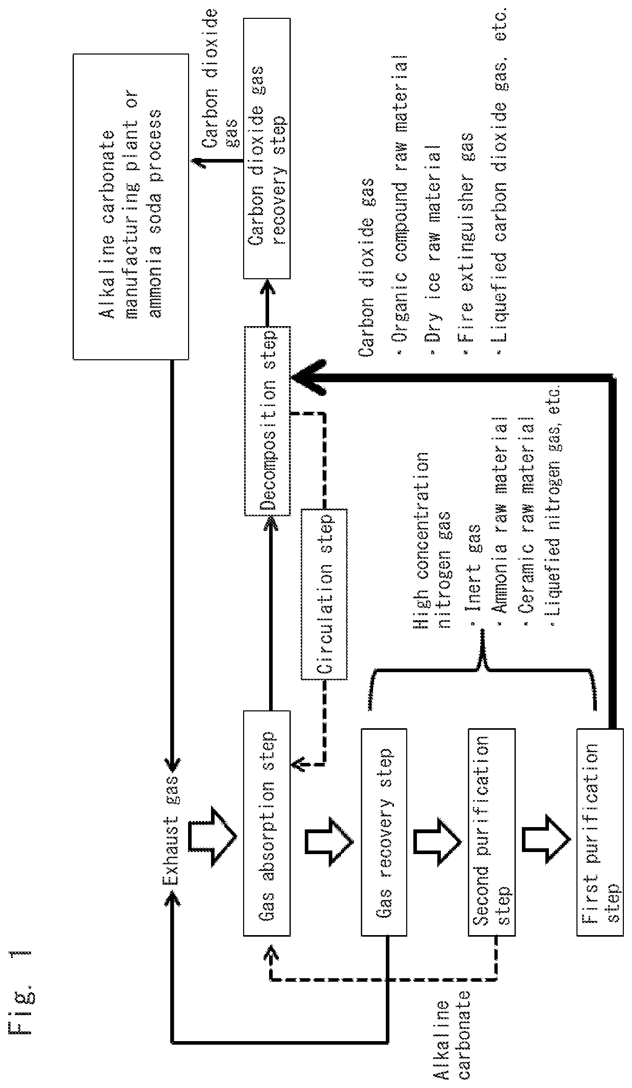
[0140]Exhaust gas was adjusted to have a composition such that carbon dioxide gas, nitrogen gas and oxygen gas were contained in amounts of 42.5 volume %, 57 volume %, and 0.5 volume %, respectively, when the sum of the carbon dioxide gas, the nitrogen gas and the oxygen gas was 100 volume %. The thus-prepared exhaust gas was supplied in an amount of 60,000 cm3 / hour to an aqueous solution containing potassium carbonate in a concentration of 60 mass %. At this time, the aqueous potassium carbonate solution had a temperature (reaction temperature) of 70° C. and was kept being stirred.

[0141]The exhaust gas was supplied for one hour, and the resultant aqueous solution was sent to a decomposition step (first purification step).

Gas Recovery Step:

[0142]A gas obtained as a result of bringing the exhaust gas into contact with the aqueous potassium carbonate solution in the gas absorption step was recovered. The gas contained carbon dioxide gas, nitrogen gas and oxygen gas...

example 2

Gas Absorption Step:

[0151]Exhaust gas was adjusted to have a composition such that carbon dioxide gas, nitrogen gas and oxygen gas were contained in amounts of 42.5 volume %, 57 volume %, and 0.5 volume %, respectively, when the sum of the carbon dioxide gas, the nitrogen gas and the oxygen gas was 100 volume %. The thus-prepared exhaust gas was supplied in an amount of 26,000 cm3 / hour to an aqueous solution containing potassium carbonate in a concentration of 17.5 mass %. At this time, the aqueous potassium carbonate solution had a temperature of 25° C. and was kept being stirred.

[0152]The exhaust gas was supplied for 50 minutes, and the resultant aqueous solution was sent to a decomposition step (first purification step).

Gas Recovery Step:

[0153]A gas obtained as a result of bringing the exhaust gas into contact with the aqueous potassium carbonate solution in the gas absorption step was recovered. The gas contained carbon dioxide gas, nitrogen gas and oxygen gas in amounts of 26 v...

example 3

Gas Absorption Step:

[0161]Exhaust gas was adjusted to have a composition such that carbon dioxide gas, nitrogen gas and oxygen gas were contained in amounts of 42.5 volume %, 57 volume %, and 0.5 volume %, respectively, when the sum of the carbon dioxide gas, the nitrogen gas and the oxygen gas was 100 volume %. The thus-prepared exhaust gas was supplied in an amount of 26,000 cm3 / hour to an aqueous solution containing 10 mass % of potassium carbonate and 10 mass % of potassium bicarbonate. At this time, the aqueous solution had a temperature of 25° C. and was kept being stirred.

[0162]The exhaust gas was supplied for 30 minutes, and the resultant aqueous solution was sent to a decomposition step.

Gas Recovery Step:

[0163]A gas obtained as a result of bringing the exhaust gas into contact with the aqueous solution containing potassium carbonate in the gas absorption step was recovered. The gas contained carbon dioxide gas, nitrogen gas and oxygen gas in amounts of 26 volume %, 73.4 vol...


PUM

PropertyMeasurementUnit
Volume ratioaaaaaaaaaa

Abstract

The present invention provides a method including: a gas absorption step of bringing exhaust gas into contact with an aqueous solution containing alkaline carbonate, so that carbon dioxide gas in the exhaust gas is allowed to react therewith, thereby obtaining an aqueous solution containing alkaline bicarbonate; a gas recovery step of recovering a gas containing nitrogen gas and oxygen gas obtained as a result of the gas absorption step; a decomposition step of decomposing at least a part of the alkaline bicarbonate obtained in the gas absorption step into the alkaline carbonate and the carbon dioxide gas; a circulation step of circulating at least a part of the alkaline carbonate obtained in the decomposition step to the gas absorption step; and a carbon dioxide gas recovery step of bringing a gas containing the carbon dioxide gas obtained as a result of the decomposition step into contact with an aqueous solution, thereby recovering the carbon dioxide gas obtained in the decomposition step.

Description

TECHNICAL FIELD[0001]The present invention relates to a novel method for separating and recovering carbon dioxide gas as well as nitrogen gas and oxygen gas from exhaust gas. More specifically, the present invention relates to a novel method for efficiently separating and recovering high purity carbon dioxide gas as well as nitrogen gas with high purity with the use of an inexpensive inorganic compound.BACKGROUND ART[0002]Fossil fuels have long enriched the life of humankind. However, if these fuels are used at this rate, the global environment will evidently be destroyed by the excessive emission of greenhouse gases as typified by carbon dioxide gas. Accordingly, decarbonation (reducing the amount of carbon dioxide gas) has been considered in all parts of the world as a way to tackle this top priority issue that all mankind faces. This challenge has been discussed from various perspectives such as the promotion of energy saving, the widespread use of regenerated energy, and the fix...

Claims


Application Information

Patent Timeline
IPC IPC(8): B01D53/78B01D53/62B01D53/75B01D53/94
CPCB01D53/78B01D53/62B01D53/75B01D2256/10B01D2251/606B01D2257/504B01D2255/1021B01D53/94C01B32/50C01B21/0494B01D53/96C01B2210/0004C01B2210/0003C01B2210/0045B01D53/14B01J23/42C01B21/04B01D2251/304B01D2258/0283B01D2251/604B01D2251/306B01D2252/102B01D2257/104B01D2251/202B01D53/343B01D53/8671
Inventor KUSUNOKI, MASAOTANAKA, HIROKITAMAKI, YOSHIMITSUNODA, DAI
Owner TOKUYAMA CORP
Learn More