
Method for protecting an inner wall of a shaft furnace

a technology for shaft furnaces and inner walls, which is applied in the direction of furnaces, manufacturing converters, lighting and heating apparatus, etc., can solve the problems of increasing erosion, damage and/or high heat loads, and affecting the operation of the furna

Pending Publication Date: 2022-03-10
PAUL WURTH SA
View PDF0 Cites 0 Cited by
  • Summary
  • Abstract
  • Description
  • Claims
  • Application Information

AI Technical Summary

Benefits of technology

The patent describes a method for creating or repairing a layer of protective material in a shaft furnace to prevent damage caused by the heat and other materials present during the production process. This layer of protective material can be injected on demand, allowing for maintenance without stopping the production process. The protective material can include various materials commonly found in the burden material, such as slag, coal, or ore. This method ensures the prolonged life of the furnace's cooling elements and prevents deformation caused by heat loads.

Problems solved by technology

During shaft furnace operations, some areas of the furnace wall are subject to more erosion, damage and / or high heat loads than others.
Excessive amount of heat can weaken the cooling staves, deforms them and eventually leads to irreversible damage.
Excessive erosion of the cooling staves, which can be caused by the abrasive action of the flow of burden material, can remove the metal around the cooling circuit which eventually becomes exposed, leaking coolant fluid into the furnace.
Additionally, the above solutions do not provide any means to prevent the negative effects of the furnace operations on the cooling staves.
The known solutions only provide temporary protection and do not offer the possibility to maintain the copper staves.
Solutions to protect the stave lining inside the furnace are limited by the resistance to heat or erosion of the material used, and involve production loss during maintenance operations.

Method used


Image

  • Method for protecting an inner wall of a shaft furnace
  • Method for protecting an inner wall of a shaft furnace

Examples


Embodiment Construction

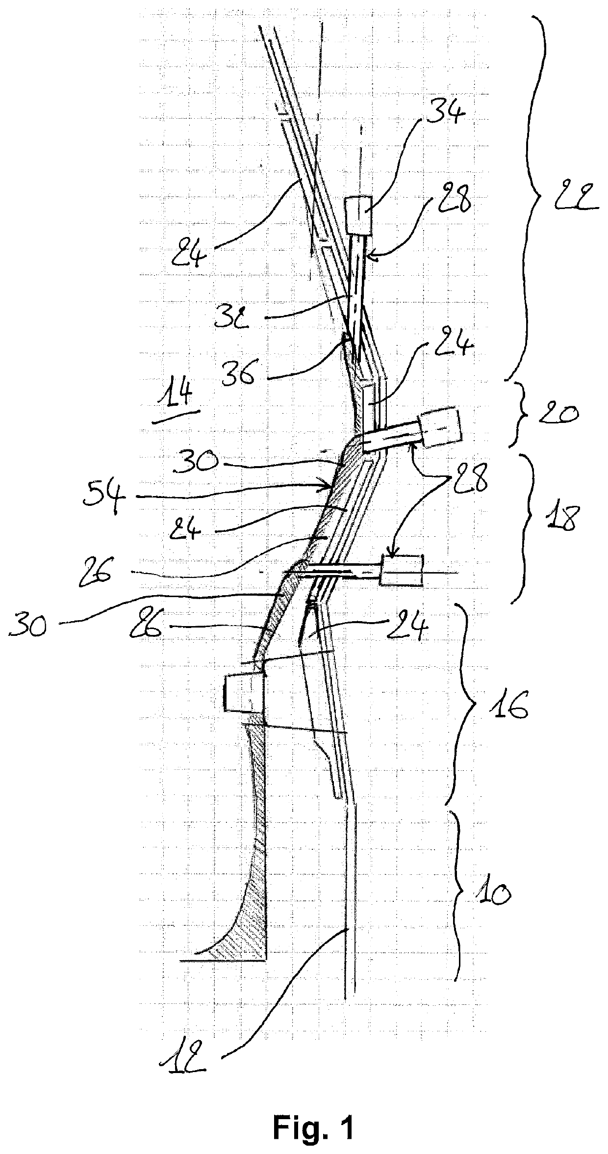
[0029]A preferred embodiment of the method will be described applied in the context of a shaft furnace, generally a blast furnace. Such a shaft furnace is partially shown in FIG. 1, comprising a lower part with a hearth portion 10 where iron and slag are collected, and a shell having an inner wall 12 forming a generally cylindrical barrel which extends upwardly from the hearth portion 10. For a better understanding, reference 14 represents part of the furnace interior volume, wherein, in operation, burden material (not shown) is charged.

[0030]As shown in FIG. 1, the inner wall 12 comprises portions of different diameters. From the hearth portion 10 to the top, the shaft furnace comprises a tuyere surrounding 16, a bosh portion 18, a belly portion 20 and a stack portion 22. Above the stack portion 22, the shaft furnace further comprises a throat and a charging installation (not shown) for charging material into the shaft furnace.

[0031]The inner wall 12 is covered by a lining of heat ...


PUM

PropertyMeasurementUnit
gravityaaaaaaaaaa
angleaaaaaaaaaa
round shapeaaaaaaaaaa

Abstract

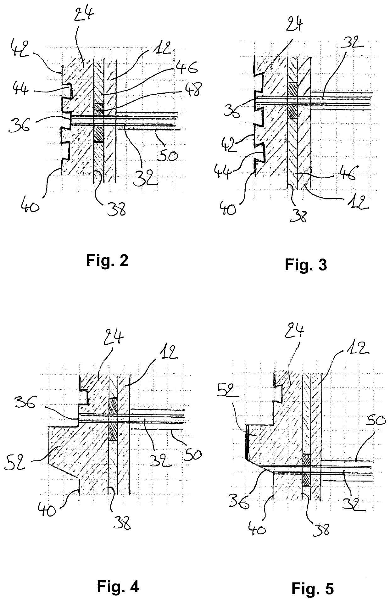
A method for protecting an inner wall (12) of a shaft furnace, the method comprising the steps of: providing at least one injection device (28) through the inner wall (12) of the shaft furnace, the injection device (28) being configured to inject protective material into the shaft furnace; and injecting on demand the protective material into the shaft furnace through the injection device (28), in such a manner that the protective material builds up to form a protection wall between the interior of the shaft furnace and the furnace wall (12).

Description

TECHNICAL FIELD[0001]The present disclosure relates to a method for operating a shaft furnace, like for example a blast furnace. The present disclosure particularly relates to a method for protecting an inner wall of a shaft furnace.BACKGROUND[0002]The inner walls of a shaft furnace are typically covered by a lining of cooling staves to dissipate heat generated by the extreme temperature applied during furnace operations and prevent the furnace wall from damage caused by extreme heat.[0003]A cooling stave is generally a heat conductive plate made of copper or steel or alloys, equipped with a cooling circuit and having connection means to be attached to a furnace wall. The cooling circuit may be a hollow path running inside the cooling stave and having any desired design. The circuit is fed with a circulating cooling fluid, like for example water that is then extracted from the cooling stave carrying heat away from the furnace wall.[0004]During shaft furnace operations, some areas of...

Claims


Application Information

Patent Timeline
Patent Type & Authority Applications(United States)
IPC IPC(8): F27D1/16F27B1/14F27D1/00
CPCF27D1/1678F27B1/14F27D1/0003F27D2001/047F27D1/1642F27D2001/161F27D1/1626F27D1/1647F27D2001/0046C21B7/06C21B9/06C21C5/441
Inventor MAGGIOLI, NICOLASMUSTAFA, ESMER
Owner PAUL WURTH SA
Learn More