
Implant for non-luminal area

a non-luminal, implant technology, applied in the direction of prosthesis, surgery, superimposed coating process, etc., can solve the problems of affecting the basic function of the medical instrument, the implant must be removed, and the human body inducing various complications, so as to reduce the influence of the remaining parylene layer on the body, reduce the effect of suppressive elution of magnesium alloy, and reduce the influence of the remaining parylene layer

Pending Publication Date: 2022-01-13
JAPAN MEDICAL DEVICE TECH
View PDF0 Cites 0 Cited by
  • Summary
  • Abstract
  • Description
  • Claims
  • Application Information

AI Technical Summary

Benefits of technology

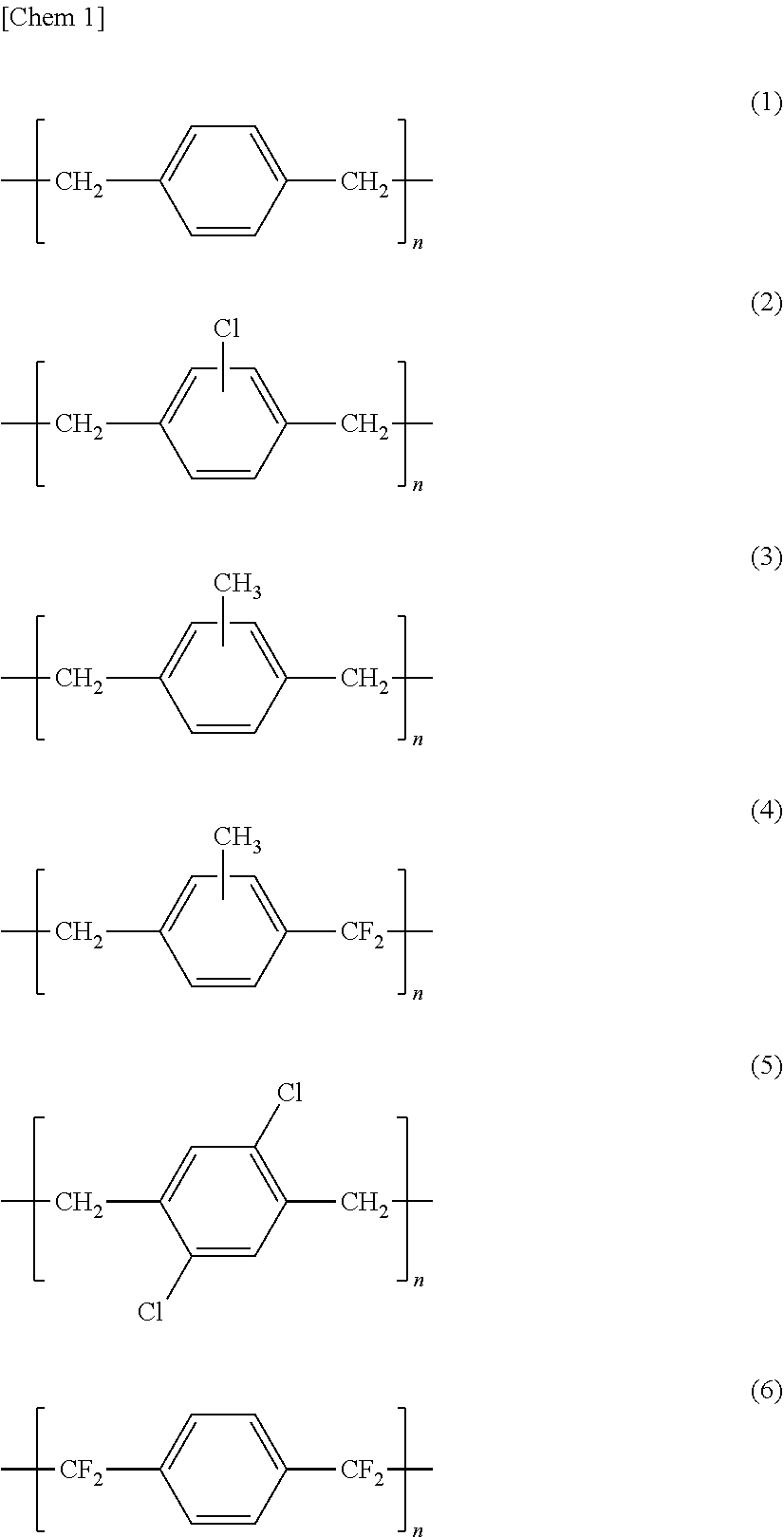
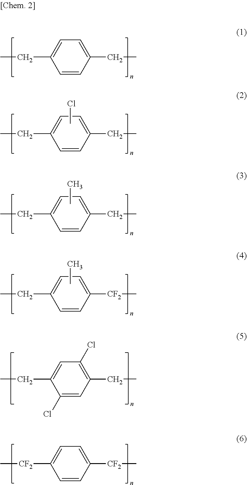
The present invention relates to a method for improving the corrosion resistance and mechanical strength of a magnesium alloy implant for non-luminal region applications. This is achieved by forming a magnesium fluoride layer on the surface of the magnesium alloy and then adding a parylene layer on top of it. The magnesium fluoride layer is biodegraded and absorbed into the body, while the parylene layer is not. The combination of magnesium fluoride and parylene layers provides better corrosion resistance than either layer alone. The magnesium alloy used in the invention is free from rare metals and aluminum, making it safe for human use. It has excellent deformability and mechanical properties and is free of coarse precipitates that can lead to fractures. The magnesium alloy should have a content of unavoidable impurities such as Fe, Ni, Co, and Cu lower than 10 ppm, preferably without Co.

Problems solved by technology

However, the implants remaining in the human body after given treatment would induce various complications in the human body.
Accordingly, there is an inconvenience such that the inserted implant must be removed from the human body through additional treatment after achieving the purposes of the implant.
Where the degradation rate of the magnesium alloy is too fast, the magnesium alloy will lose stability before recovery of the damaged tissues, resulting in failure of basic function as the medical instrument.
On the contrary, if the degradation rate of the magnesium alloy is too slow, it would result in a higher risk such as complication.

Method used


Image

  • Implant for non-luminal area
  • Implant for non-luminal area
  • Implant for non-luminal area

Examples


production examples 1 and 2

of Magnesium Alloy

[0106]High purity ground metals of Mg, Zn, Mn, and Zr were prepared as raw materials. Respective components were weighted so as to constitute the component concentration shown in Table 1, and were thrown into a crucible, and were molten at 730° C. Each melt was stirred in the crucible, and was cast to form an ingot. Each of the thus-obtained magnesium alloys of Production Examples 1 and 2 was made to have a blending ratio of the main component within the range of the present invention. Rare earth elements and aluminum were not contained in the raw materials even as unavoidable impurities. Magnesium was provided from a magnesium ground metal of purity level of 99.99% with low concentration of impurity Cu, and molten alloy in the crucible were subjected to iron-extraction treatment so as to remove iron and nickel from the molten alloy. Impurity concentrations of the thus obtained samples were measured using an ICP emission spectrometer (AGILENT 720 ICP-OES made by Ag...

production example 3

[0109]High purity ground metals of Mg, Zn, Mn, and Zr were prepared as raw materials. Respective components were weighted so as to constitute the component concentration shown below, and were thrown into a crucible, and were molten at 730° C. Each melt was stirred in the crucible, and was cast to form an ingot. Rare earth elements and aluminum were not contained in the raw materials even as unavoidable impurities.

[0110]Magnesium was provided from a magnesium ground metal of purity level of 99.99% with low concentration of impurity Cu, and molten alloy in the crucible were subjected to iron-extraction treatment so as to remove iron and nickel from the molten alloy.

[0111]Impurity concentrations of the thus obtained ingot were measured using an ICP emission spectrometer (AGILENT 720 ICP-OES made by Agilent Technologies).

[0112]Component concentration (w %) of the obtained ingot was as follows, and the ingot did not contain aluminum and rare earths.

[0113]Mg Remnant, Zn 1.5%, Mn 0.4%, Zr ...

example 1

[0125]The magnesium alloy substrate A with the mirror surface was immersed in a 27M aqueous hydrofluoric acid solution and shaken at 100 rpm. The sample taken out of the solution after 24 hours was thoroughly ultrasonically cleaned with water and acetone, and then dried at 60° C. under reduced pressure for 24 hours. Accordingly, a sample having a magnesium fluoride layer (thickness 1 μm) was obtained. A parylene layer C with a thickness of 500 nm was further formed on the sample by CVD method so as to obtain a sample having a parylene layer on a magnesium fluoride layer.


PUM

PropertyMeasurementUnit
grain size distributionaaaaaaaaaa
thicknessaaaaaaaaaa

Abstract

A bioabsorbable implant for non-luminal region comprising: a core structure including a magnesium alloy having a predetermined shape; a first corrosion-resistant layer containing a magnesium fluoride layer as a main component formed on the core structure via fluorination of a surface of the magnesium alloy; and a second corrosion-resistant layer containing a parylene formed on the magnesium fluoride layer.

Description

CROSS REFERENCE TO THE RELATED APPLICATION[0001]This application is a continuation application, under 35 U.S.C § 111(a) of international application No. PCT / JP2020 / 013768, filed Mar. 26, 2020, which claims priority to Japanese patent applications No. 2019-062874 filed Mar. 28, 2019 and No. 2020-001520 filed Jan. 8, 2020, the entire disclosures of which are herein incorporated by reference as a part of this application.FIELD OF THE INVENTION[0002]The present invention relates to an implant for non-luminal region made of a biodegradable magnesium alloy in which the surface of the magnesium alloy is modified by covering the surface of the magnesium alloy with a corrosion inhibitory layer.[0003]The implant for non-luminal region according to the present invention can be used as an implant for orthopedic surgery, oral surgical surgery, plastic surgery, cerebral surgery, and others.BACKGROUND OF THE INVENTION[0004]In modern medical technology, implants are widely applied as supports for s...

Claims


Application Information

Patent Timeline
Patent Type & Authority Applications(United States)
IPC IPC(8): A61L27/58A61L27/04A61L27/30C22C23/04C23C28/00
CPCA61L27/58A61L27/047A61L27/306A61L2420/02C23C28/00A61L2430/02A61L2430/12C22C23/04A61L31/10C23C22/34B05D1/60B05D2202/20B05D2350/60A61L31/022A61L31/088A61L31/148A61L2300/608C25F3/18C08L65/04
Inventor YAMASHITA, SHUZOSASAKI, MAKOTOWADA, AKIRA
Owner JAPAN MEDICAL DEVICE TECH
Learn More