
Deck clip

Inactive Publication Date: 2006-03-23
WOOD HAVEN
View PDF23 Cites 54 Cited by
  • Summary
  • Abstract
  • Description
  • Claims
  • Application Information

AI Technical Summary

Benefits of technology

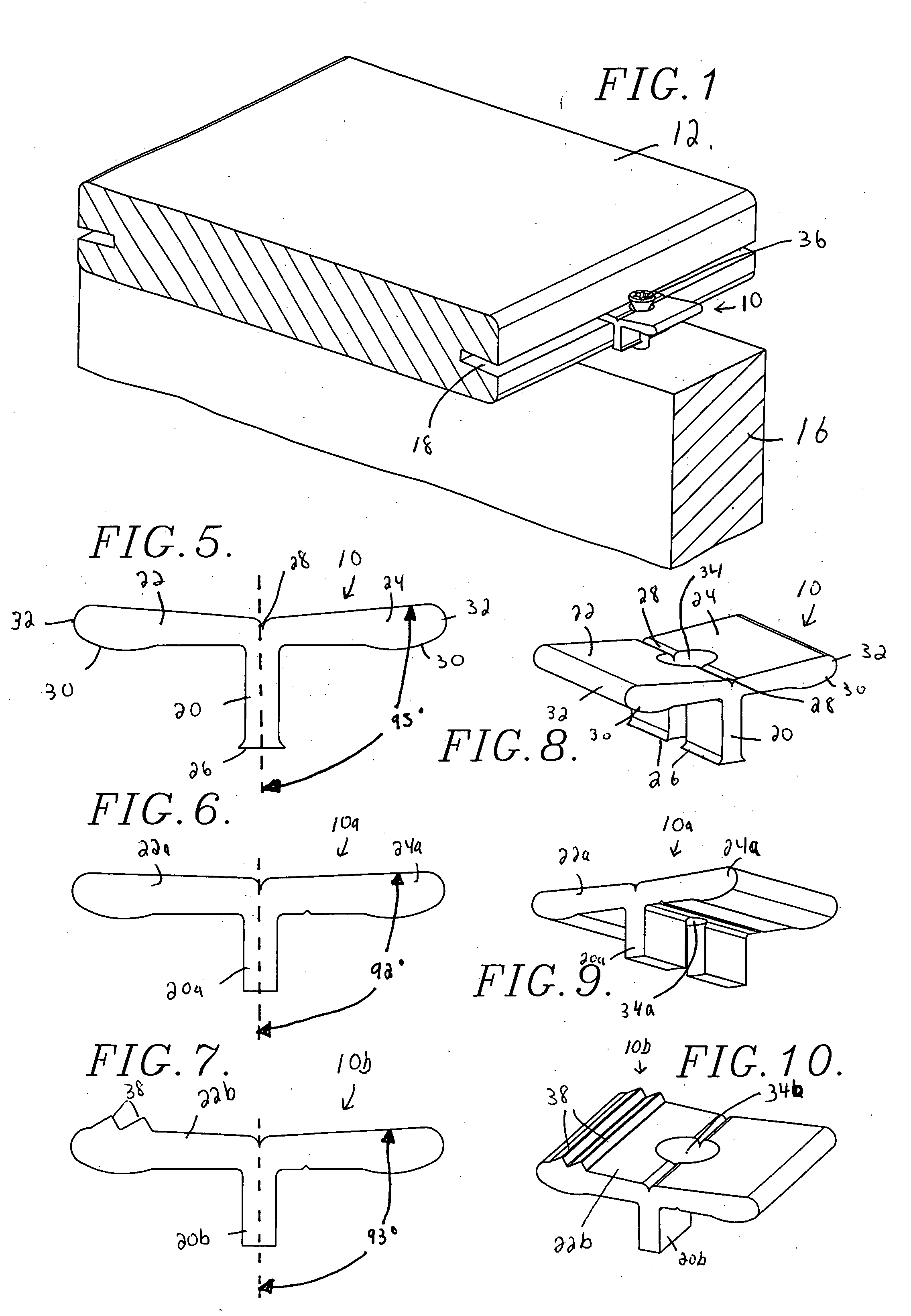
[0008] The present invention solves the above-described problems and provides a distinct advance in the art of deck clips. More particularly, the present invention provides a deck clip that is stronger, easier to install, more effective at securing boards to an underlying joist, and more effective at preventing relative movement between adjacent boards.
[0009] A deck clip constructed in accordance with one embodiment of the present invention broadly comprises a generally vertically extending leg; and a pair of arms extending from an upper edge of the leg. Each arm is configured for insertion into a slot of a deck board and presents an enlarged lobe. When the deck clip is screwed to a deck joist, the lobes grip the deck boards and hold them tight against the joist. The shape of the lobes increases the gripping force between the deck clip and the deck boards. As adjacent boards are hammered or otherwise pushed together (to achieve the desired gap between the boards), the lobes exert additional pressure on the boards to firmly hold them in place. The lobes thus facilitate the gripping of the boards and help maintain the desired gap between adjacent boards for the life of the deck.
[0010] A deck clip constructed in accordance with another embodiment of the present invention broadly comprises a generally vertically extending leg; and a pair of arms extending from an upper edge of the leg. Each arm is configured for insertion into a slot of a deck board and presents a curved edge. The curved edges slide easily into the slots of the boards for facilitating insertion of the arms into the slots.
[0011] A deck clip constructed in accordance with another embodiment of the present invention broadly comprises a generally vertically extending leg; and a pair of arms extending from an upper edge of the leg. Each arm is configured for insertion into a slot of a deck board and is angled slightly upwardly relative to the leg. This configuration allows the ends of the arms to flex slightly upwardly when the deck clip is screwed to a deck joist to hold the deck boards down with a spring-like effect. The slots in the deck boards may also be angled slightly relative to horizontal to shed water which drains between adjacent deck boards.
[0012] Decking material constructed in accordance with another embodiment of the invention broadly comprises at least two boards, each board presenting an elongated slot; and at least one deck clip for securing the boards to an underlying support. The deck clip comprises a generally vertically extending leg; a pair of arms extending from an upper edge of the leg and each configured for insertion into a slot of one of the boards; a screw hole extending through the arms and the leg; and a screw configured to be inserted in the screw hole and driven into the underlying support. The leg is sized so it does not touch the underlying support when the screw is driven into the support to resist corrosion of the deck clip.
[0013] The deck clips of all of the embodiments of the present invention are preferably extruded from marine grade aluminum to resist corrosion and provide superior holding strength. The deck clips are preferably attached to the deckjoists with stainless steel screws with Star drives.

Problems solved by technology

Homeowners are also building more elaborate and expensive decks and don't want to be limited to conventional treated “soft” lumber for the primary deck boards.
Unfortunately, prior art deck clips suffer from several limitations which limit their utility.
For example, many prior art clips are made of plastic and easily break when installed.
Even when they don't break, these plastic clips don't provide significant holding force, resulting in loose deck boards.
Prior deck clips are also difficult to install and do not effectively grip the deck boards, often causing the boards to shift relative to one another, especially over time, resulting in uneven gaps between the boards.

Method used


Image

  • Deck clip
  • Deck clip
  • Deck clip

Examples


Embodiment Construction

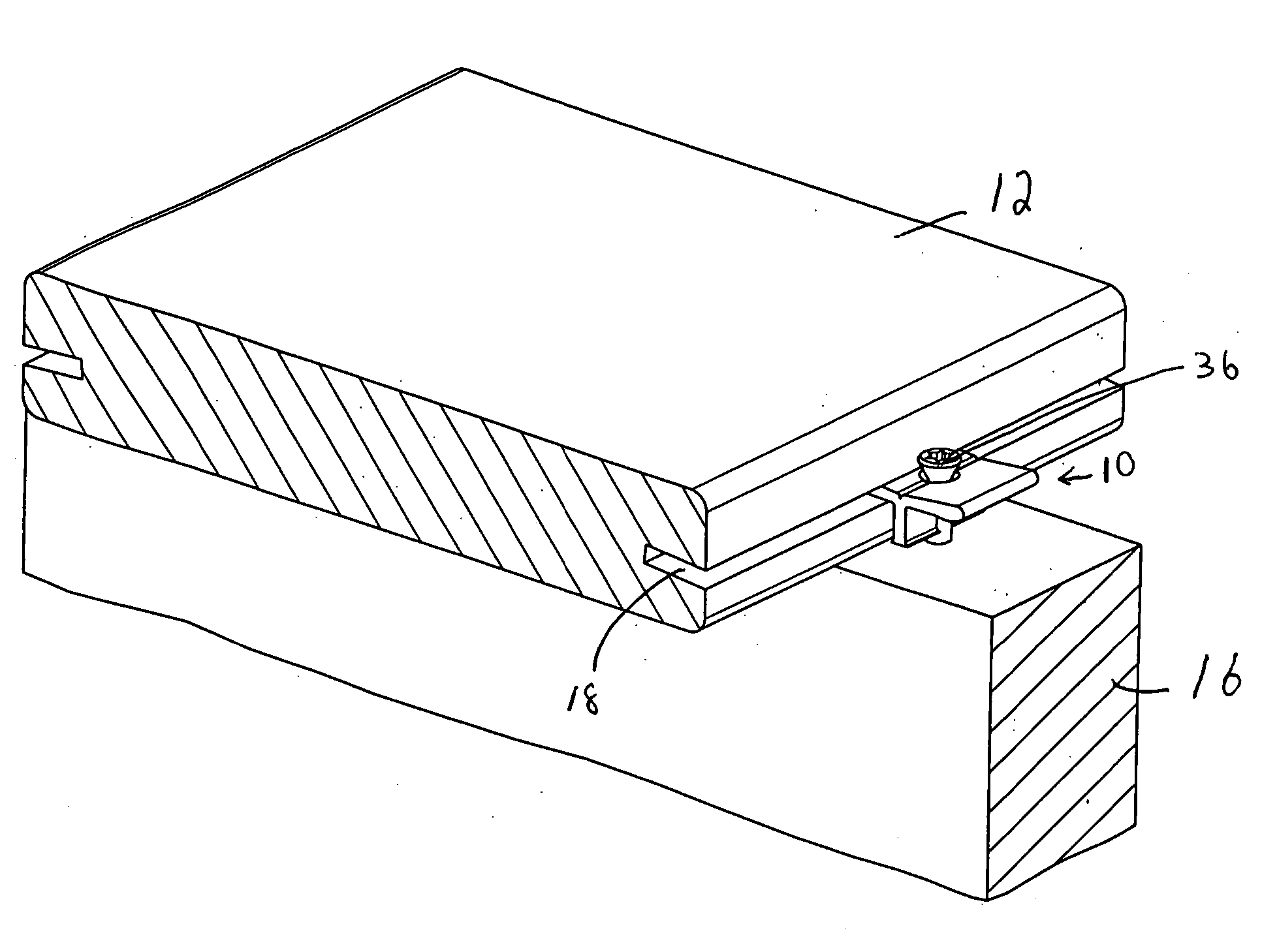
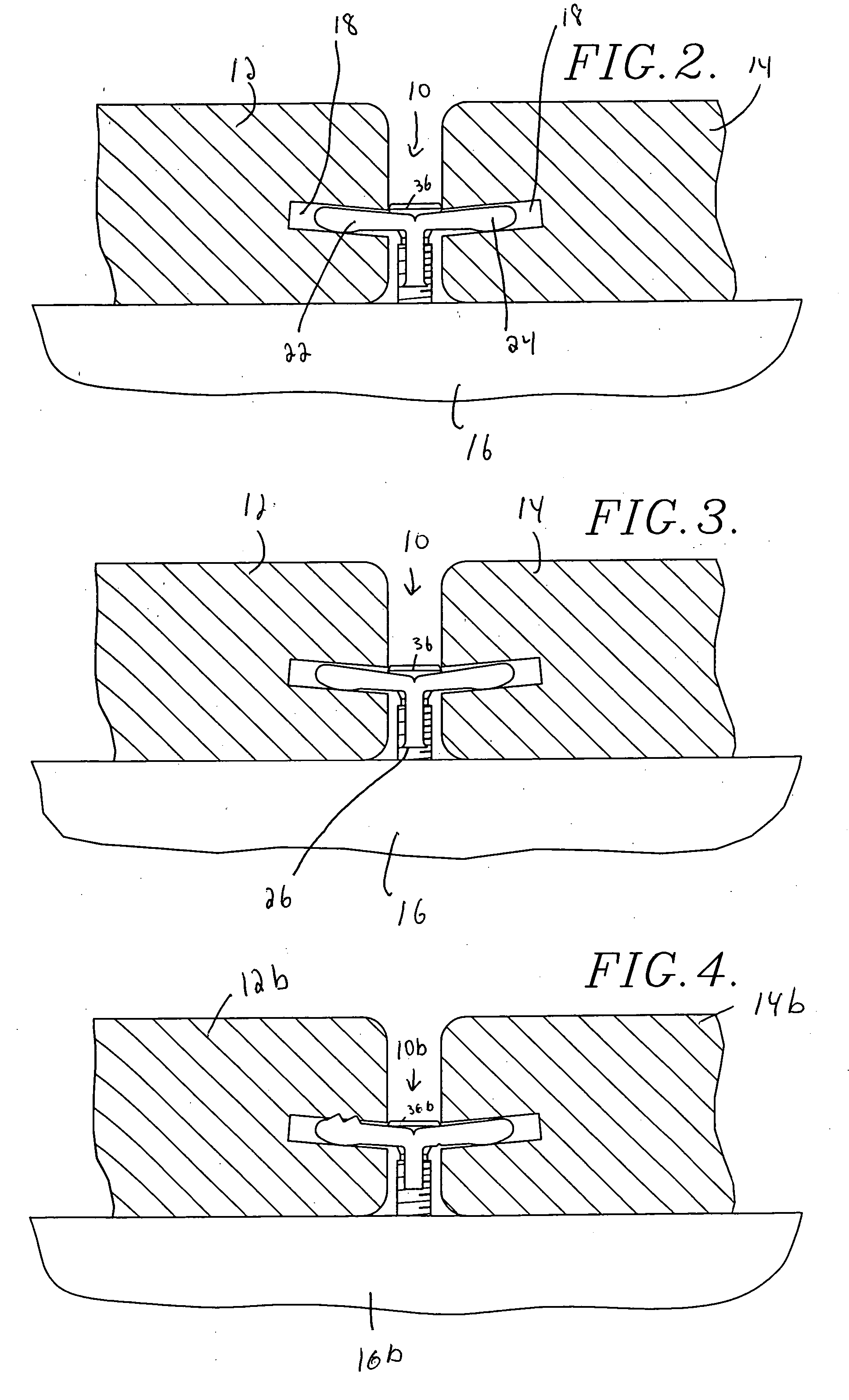
[0027] Turning now to the drawing figures, and particularly FIGS. 1, 2, 3, 5 and 8, a deck clip 10 constructed in accordance with a first preferred embodiment of the invention is shown securing deck boards 12,14 to an underlying support 16. The deck boards 12,14 are conventional and are preferably formed of a hard wood material such as cumaru, ipe, or tauari; however, they may be formed of other types of wood, composite materials, synthetic resins, or any other materials commonly used for decking.

[0028] As shown, each deck board 12,14 has at least one elongated, pre-grooved or biscuitjointer slot 18 formed therein. The slots 18 are preferably formed between 3 / 8″-5 / 16″ from the bottom of the boards, the exact positioning depending on the thickness of the boards. The slots 18 are preferably approximately ⅛″ to ¼″ tall (from top to bottom) and approximately ½″ deep (from left to right). As best illustrated in FIGS. 2-4, the slots 18 are preferably slightly angled relative to horizonta...


PUM


Abstract

A deck clip comprises a generally vertically extending leg; and a pair of arms extending from an upper edge of the leg. Each arm is configured for insertion into a slot of a deck board and presents an enlarged lobe. When the deck clip is screwed to a deck joist, the lobes grip the deck boards and hold them tight against the joist. The shape of the lobes increases the gripping force between the lobes and the deck boards as adjacent boards are hammered or otherwise pushed together. The lobes facilitate the gripping of the boards and help maintain the desired gap between adjacent boards for the life of the deck.

Description

RELATED APPLICATION [0001] The present application claims priority benefit, with regard to all common subject matter, of earlier-filed U.S. provisional patent application titled “DECK CLIP”, application Ser. No. 60 / 598,767, filed Aug. 4, 2004. The identified earlier-filed provisional patent application is hereby incorporated into the present application by specific reference.BACKGROUND OF THE INVENTION [0002] 1. Field of the Invention [0003] The present invention relates to decking material. More particularly, the invention relates to a deck clip for more effectively securing deck boards to an underlying support such as a deck joist. [0004] 2. Description of the Prior Art [0005] Decks and other outdoor structures are becoming increasingly popular as homeowners spend more time outside. Homeowners are also building more elaborate and expensive decks and don't want to be limited to conventional treated “soft” lumber for the primary deck boards. For example, it is now common for decks t...

Claims


Application Information

Patent Timeline
IPC IPC(8): E04B9/00
CPCE04F15/02F16B12/125F16B5/002E04F2201/05E04F2015/02094
Inventor GUFFEY, JAMES KING
Owner WOOD HAVEN
Learn More