
System and Method for Establishing a Graphite Ground System

a graphite ground and graphite technology, applied in the field of graphite ground system system and graphite ground system, can solve the problems of limited lifespan, high construction/maintenance cost, and difficulty of conventional grounding system,

Pending Publication Date: 2021-11-18
LIMONGI ARMANDO
View PDF20 Cites 0 Cited by
  • Summary
  • Abstract
  • Description
  • Claims
  • Application Information

AI Technical Summary

Benefits of technology

The patent is about a process for making an area able to allow substances to be poured into it. This improves the contact between the area and the grounding element, which helps to reduce electrical resistance.

Problems solved by technology

With the recent implementation of microprocessors, the conventional grounding systems have difficulties because the resistance needed must be lower than the normalized ones.
1. Electrochemical influence on the ground rod (corrosion); all metals used for grounding systems inserted into the soil corrode due to chemical reactions between the area humidity and the electrode, chemical agents contained in the terrain, electric currents running across the terrain, electrochemical corrosion, oxygen corrosion, microbiological corrosion, galvanic corrosion, neutral salt corrosion, and corrosion due to the material's heterogeneity. The corrosion produces variable instability over time according to the soil composition, representing an increase in grounding resistance and the weakening of the electrode's material. Further, the electrode could fuse after a certain time due to atmospheric discharge or a lack of electric supply, which leaves a connected facility unprotected. Generally, current electrode materials are non-reliable with a limited lifespan in any kind of terrain.
2. Grounding electrodes or mesh sizes; in most cases, the design of the grounding electrode takes into consideration the size of the conductor that will be buried (horizontal conductor or electrode) and the different metal electrode interconnections that will form the multiple electrode ground system (vertical electrodes) which are based on the ground's resistivity and the resistance needed. Depending on the land resistivity, large and costly grounding electrodes requiring large amounts of material (conductors, ground electrodes, connections) and labor (excavations, pushing of grounding pegs, etc.) are necessary. In many cases, the installations do not have an area big enough for large grounding mesh, requiring empirical solutions and, in the worst of the cases, being unable to provide solutions using the existing technology. Large installations also are susceptible to high corrosion, which in turn results in high construction / maintenance costs and limited lifespans.
3. Maintenance; the maintenance of conventional grounding electrodes must be measured over time to test the performance of the grounding system. The maintenance process is a complex and expensive process that requires the soil to be recompressed before the electrodes can readapt to the environment. This results in an inactive period during which any connected facilities are vulnerable to ground-faults.
4. Theft; one of the biggest problems of ground systems worldwide is theft due to the use of copper in the ground systems. Copper is one of the most-stolen non-ferrous metals. When copper components are stolen, the facilities are left unprotected and out of service.

Method used


Image

  • System and Method for Establishing a Graphite Ground System
  • System and Method for Establishing a Graphite Ground System
  • System and Method for Establishing a Graphite Ground System

Examples


Embodiment Construction

[0018]All illustrations of the drawings are for the purpose of describing selected versions of the present invention and are not intended to limit the scope of the present invention. The present invention is to be described in detail and is provided in a manner that establishes a thorough understanding of the present invention. There may be aspects of the present invention that may be practiced or utilized without the implementation of some features as they are described. It should be understood that some details have not been described in detail in order to not unnecessarily obscure focus of the invention. References herein to “the preferred embodiment”, “one embodiment”, “some embodiments”, or “alternative embodiments” should be considered to be illustrating aspects of the present invention that may potentially vary in some instances, and should not be considered to be limiting to the scope of the present invention as a whole.

[0019]In reference to FIG. 1 through 7, the present inv...


PUM


Abstract

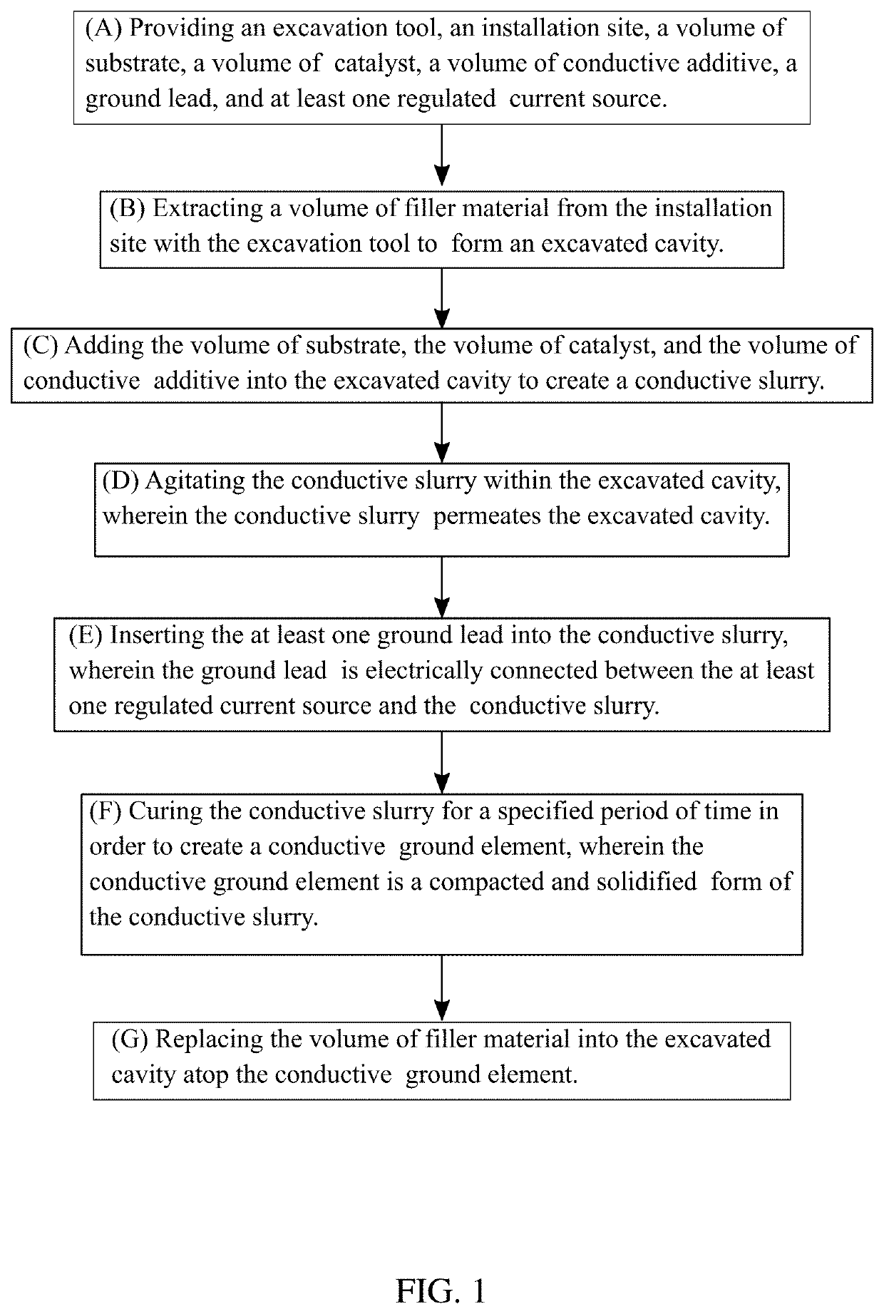
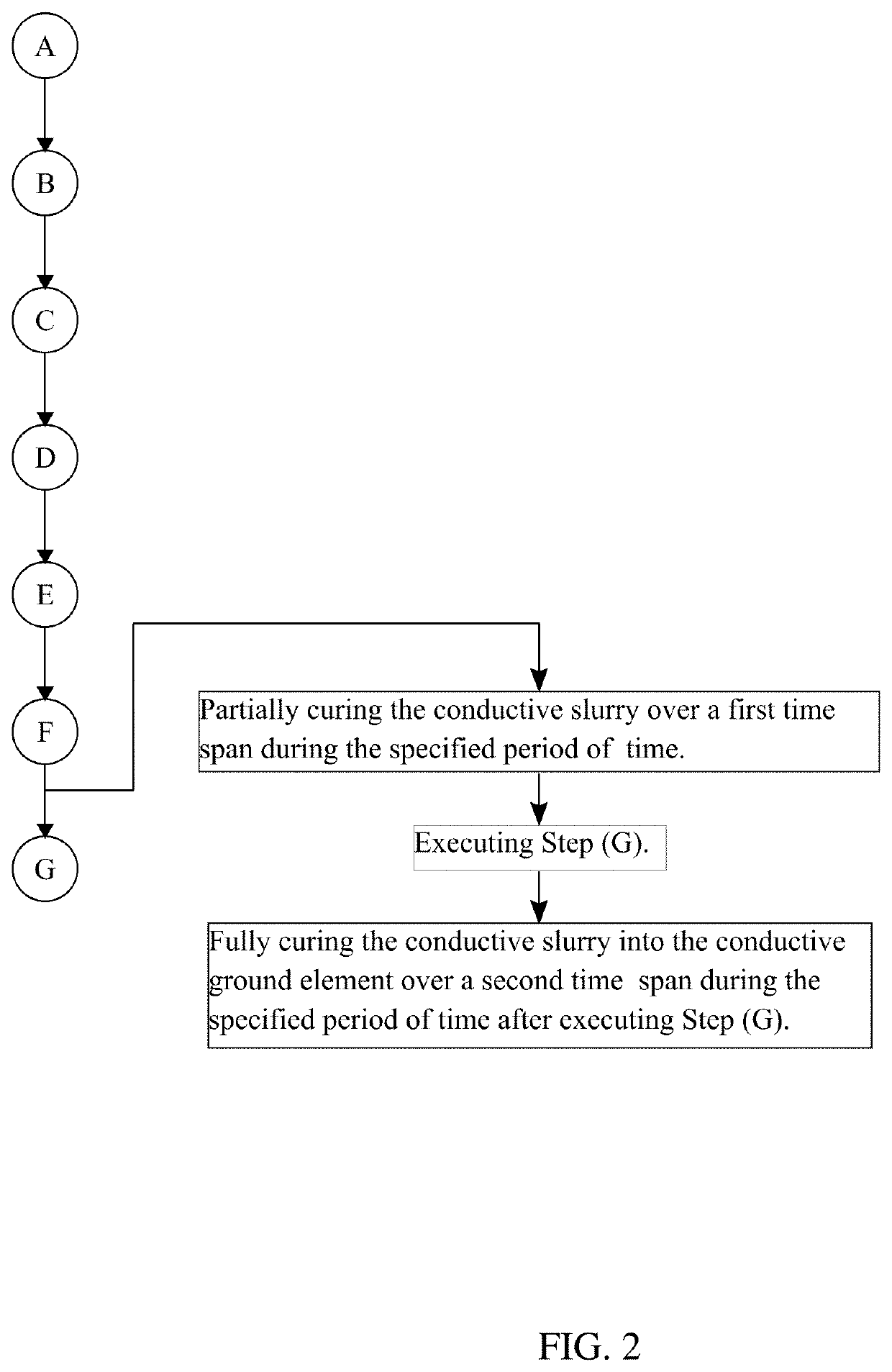
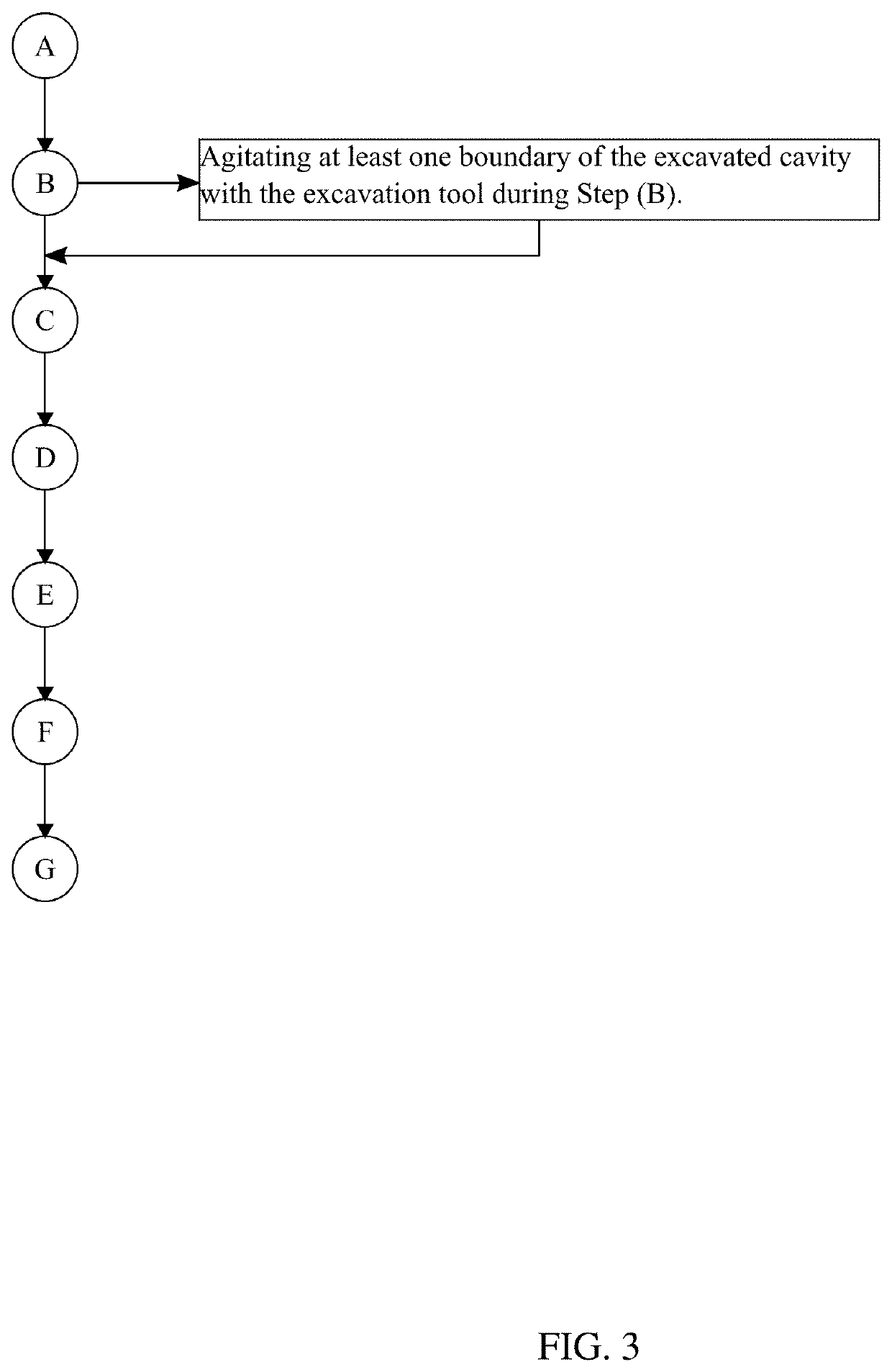
A system and method for preparing and installing a graphite ground system is able to establish a durable conductive ground suitable for use in dissipating electrical current in conjunction with larger sensitive electronic installations. The method is provided with an excavation tool, an installation site, a volume of substrate, a volume of catalyst, a volume of conductive additive, a ground lead, and at least one regulated current source. The excavation tool is used to prepare the installation site for an in-situ preparation of the volume of substrate, the volume of catalyst, and the volume of conductive additive. The resultant conductive slurry is further modified with the integration of the ground lead, whereby the regulated current source may be electrically connected to earth (electrical ground). The conductive slurry is subsequently compacted and solidified into a conductive ground element, capturing the ground lead and ensuring a consistent electrical connection to ground.

Description

[0001]The current application claims a priority to the U.S. Provisional Patent application Ser. No. 63 / 025,627 filed on May 15, 2020. The current application is filed on May 17, 2021 while May 15, 2021 was on a weekend.FIELD OF THE INVENTION[0002]The present invention relates generally to the field of electrical infrastructure and conductive materials sciences. More specifically, the present invention presents a means and method for establishing a durable, cost-effective conductive ground contact for sensitive electronic systems.BACKGROUND OF THE INVENTION[0003]Common electrodes in grounding systems include copper-well bars, copper conductors, active electrodes (chemical bars), plates, tubes, metal armors, etc. Ground systems are made according to calculations of the ground's resistivity, e.g., the resistance present in a soil's cube of one meter (Ω / m) of edge by the passage of electric current (p), and the grounding resistance value which is the resistance that will oppose the pass...

Claims


Application Information

Patent Timeline
IPC IPC(8): H01R4/66H01B1/04
CPCH01R4/66H01B1/04H02G13/40H01B5/02H01R4/62H01R43/24
Inventor LIMONGI, ARMANDO
Owner LIMONGI ARMANDO
Learn More