
Metal Plasma Thruster Cube

a thruster and metal technology, applied in the field of plasma thrusters, can solve the problems of inability to provide useful in-space propulsion, inability to scale existing electric propulsion engines such as xe ion engines and hall thrusters down to 1 w to 10 w power levels, and inability to achieve the effect of increasing energy efficiency

Active Publication Date: 2021-09-30
BENCHMARK SPACE SYST INC
View PDF1 Cites 0 Cited by
  • Summary
  • Abstract
  • Description
  • Claims
  • Application Information

AI Technical Summary

Benefits of technology

The metal plasma technology described in the patent uses less energy and is more efficient than previous methods. It charges the inductor for a very short time, resulting in less energy loss and allowing the switch to open sooner. This allows more energy to flow and contribute to thrust, compared to previous methods.

Problems solved by technology

The small mass of pico- and femto-satellites makes it difficult to provide useful in-space propulsion, as the mass of fuel needed for even small maneuvers would exceed the satellite mass.
Scaling existing electric propulsion engines such as Xe ion engines and Hall thrusters down to ˜1 W to 10 W power levels is not practical.
The unavoidable overhead mass of propellant storage tank, flow controls and plumbing in Xe ion engines and the increasing magnetic field with decreasing size in Hall thrusters makes their overall efficiency unacceptably low at these power levels.
A drawback to PTFE is that because the plasma is developed across electrically insulating PTFE, a large initiation voltage needs to be developed, and accordingly, the typical energy storage device is a high voltage capacitor that is charged to about 2 kV for each discharge cycle.
Hence the comparatively low exhaust speed of the prior art PPT makes it a less desirable option.
The prior art VAT relies on energy stored in an inductor to produce the discharge plasma across the insulator, which results in the vaporization of metal and associated thrust.
However, devices of this construction have a shorter than desirable cycle lifetime before re-deposition of a film in excess of what the inductor can vaporize at arc initiation.
This ultimately limits the number of cycles of thrust the device can provide.
Additionally, the consumption of the cathode electrode creates an asymmetry which shortens the number of usable discharges.
The tight gaps between electrodes and high electric fields in the device pose challenges for fabrication of millions of emitters that operate reliably in unison, which results in reliability and manufacturability problems.

Method used


Image

  • Metal Plasma Thruster Cube
  • Metal Plasma Thruster Cube
  • Metal Plasma Thruster Cube

Examples


Embodiment Construction

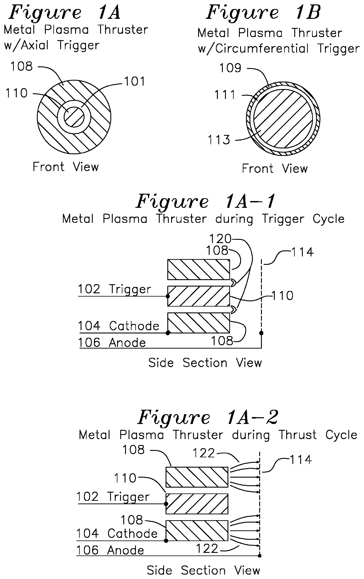
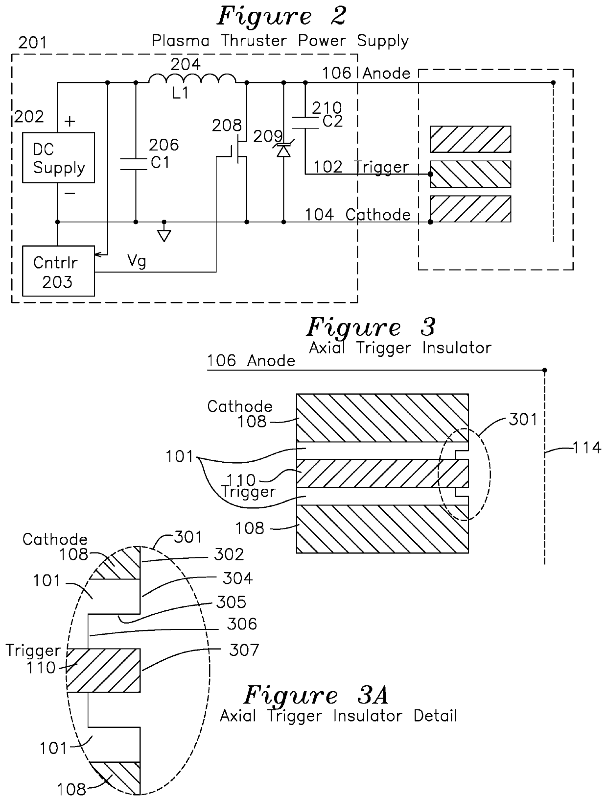
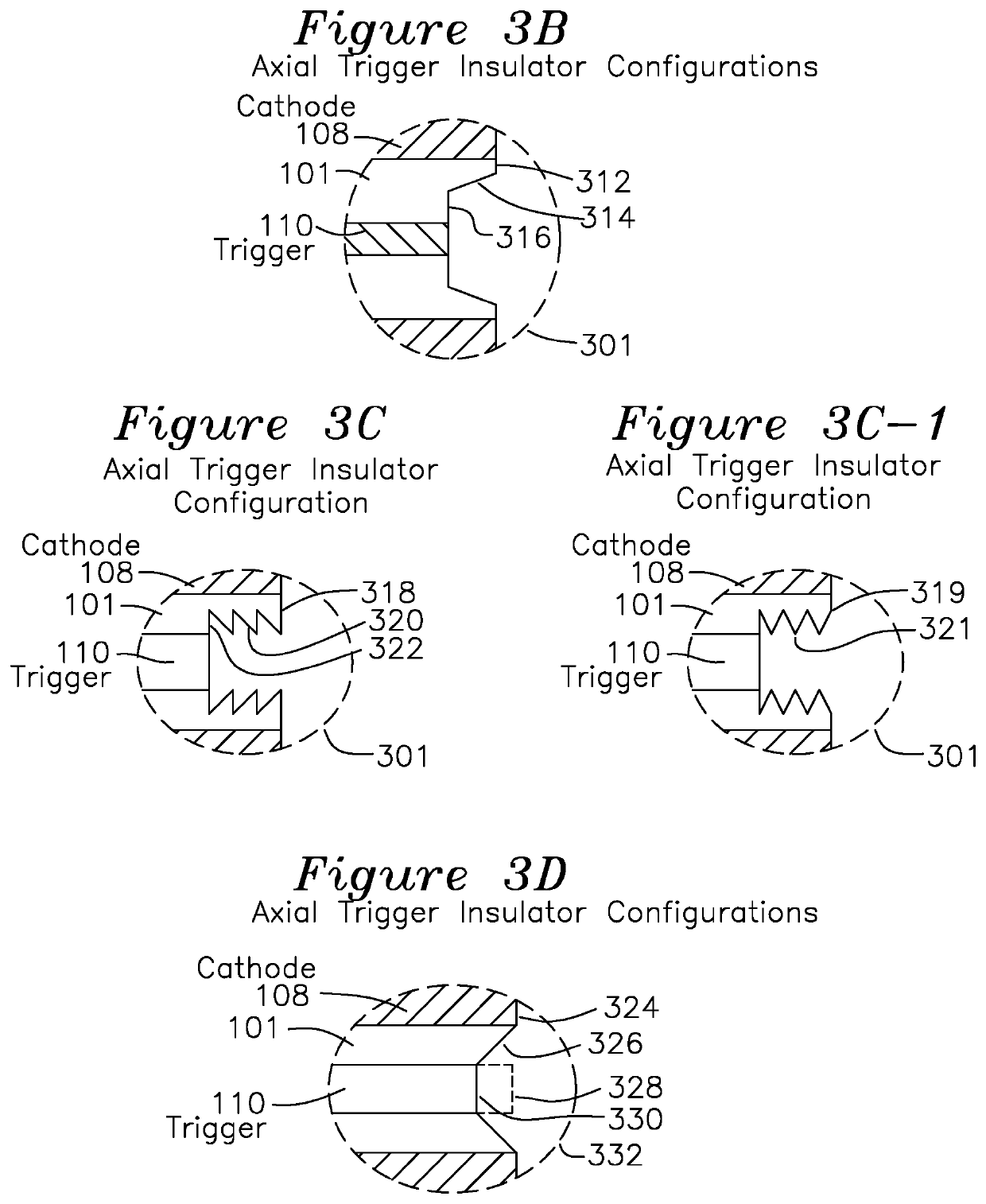
>[0050]FIG. 1A shows a front view of a first configuration for a metal plasma thruster (MPT) where a central trigger electrode 110 is separated from a cathode face 108 by an annular insulator 101 over which an initiation plasma is formed. The insulator may be formed from glass, Alumina (aluminum oxide), or any ceramic with a high melting point. FIG. 1B shows an alternative circumferential trigger configuration where a central cathode face 113 is separated by an outer circumferential trigger electrode 109 with insulator 111 positioned inside the radial extent of the trigger electrode 109. Axial trigger configuration FIG. 1A is a front view best understood in combination with side section view FIG. 3, and circumferential trigger configuration FIG. 1B is best understood in combination with side section view FIG. 4.

[0051]The cathode 108 of FIG. 1A or 113 of FIG. 1B may be formed of any material, preferably a metal which provides a comparatively high erosion rate during operation, indica...


PUM

PropertyMeasurementUnit
resistanceaaaaaaaaaa
massaaaaaaaaaa

Abstract

A pulsed metal plasma thruster (MPT) cube has a plurality of thrusters, each having a first cathode electrode and a trigger electrode separated from the first electrode by an insulator sufficient to support an initiation plasma, and a porous anode electrode positioned a separation distance from the face of all of the cathode electrodes. The cathode electrode can be either the inner electrode or the outer electrode. A power supply delivers a high voltage pulse to the trigger electrode with respect to the cathode electrode sufficient to initiate a plasma on the surface of the insulator. The plasma transfers between the anode electrode and cathode electrode of selected thrusters, thereby generating a pulse of thrust.

Description

FIELD OF THE INVENTION[0001]The present invention relates to a plasma thruster for use in a satellite. In particular, the invention relates to a metal plasma thruster (MPT) which develops pulsatile thrust through a series of plasma generation cycles.BACKGROUND OF THE INVENTION[0002]The next decade will see a dramatic increase in the number of small satellites launched into Low Earth Orbit (LEO). These satellites range in mass from <1 kg pico- and femto-satellites up to nano-satellites (1 kg to 10 kg) and micro-satellites (10 kg to 100 kg). The small mass of pico- and femto-satellites makes it difficult to provide useful in-space propulsion, as the mass of fuel needed for even small maneuvers would exceed the satellite mass. Larger satellites such as small satellites (100 kg to 500 kg) and still larger satellites have available a wide range of well tested, in-space propulsion systems such as chemical rockets (hydrazine fueled, manufactured by Busek), electrothermal arcjets (manufa...

Claims


Application Information

Patent Timeline
Patent Type & Authority Applications(United States)
IPC IPC(8): F03H1/00H05H1/48B64G1/10B64G1/40
CPCF03H1/0087H05H1/48H05H1/47B64G1/405B64G1/10H05H1/54F03H1/0043B64G1/413H05H1/2406
Inventor KRISHNAN, MAHADEVANVELAS, KATHERINE M.
Owner BENCHMARK SPACE SYST INC
Learn More