Metal/fiber-reinforced resin material composite body, method for producing same and bonding sheet

Pending Publication Date: 2021-05-06
NIPPON MICROMETAL
View PDF2 Cites 1 Cited by
  • Summary
  • Abstract
  • Description
  • Claims
  • Application Information

AI Technical Summary

Benefits of technology

The present invention provides a composite body made of metal and fiber-reinforced resin material bonded together with a resin layer, which is lightweight, easily processed, and can be produced at low costs. This composite body can be used in various applications such as electronic components and structural members due to its excellent strength. Additionally, even if the metal member is a steel material, the bonding strength between the metal member and the fiber-reinforced resin material is maintained without requiring a special surface roughening treatment. Furthermore, simultaneous heating and pressing of the metal member and fiber-reinforced resin material can lead to cost savings during production.

Problems solved by technology

Therefore, a special treatment needs to be performed for roughening and rust prevention, and also, during combining, since it is necessary to perform a high temperature process due to problems of the melt viscosity and a high melting point, there are problems regarding productivity and costs.
Therefore, a non-woven fabric made of fibers with a specific length need to be used as a reinforced fiber base material, and the reinforcing effect is limited compared to a unidirectional fiber-reinforced material and a cloth material.
However, since the polyurethane resin has low heat resistance, there are problems that it is difficult to apply it to members exposed to a high temperature, and its application is limited.
However, in Patent Literature 5, since there is no example related to a composite body of a CFRP and a metal member, the mechanical strength such as the bending strength for the composite body has not been studied.

Method used


Image

  • Metal/fiber-reinforced resin material composite body, method for producing same and bonding sheet
  • Metal/fiber-reinforced resin material composite body, method for producing same and bonding sheet
  • Metal/fiber-reinforced resin material composite body, method for producing same and bonding sheet

Examples


first embodiment

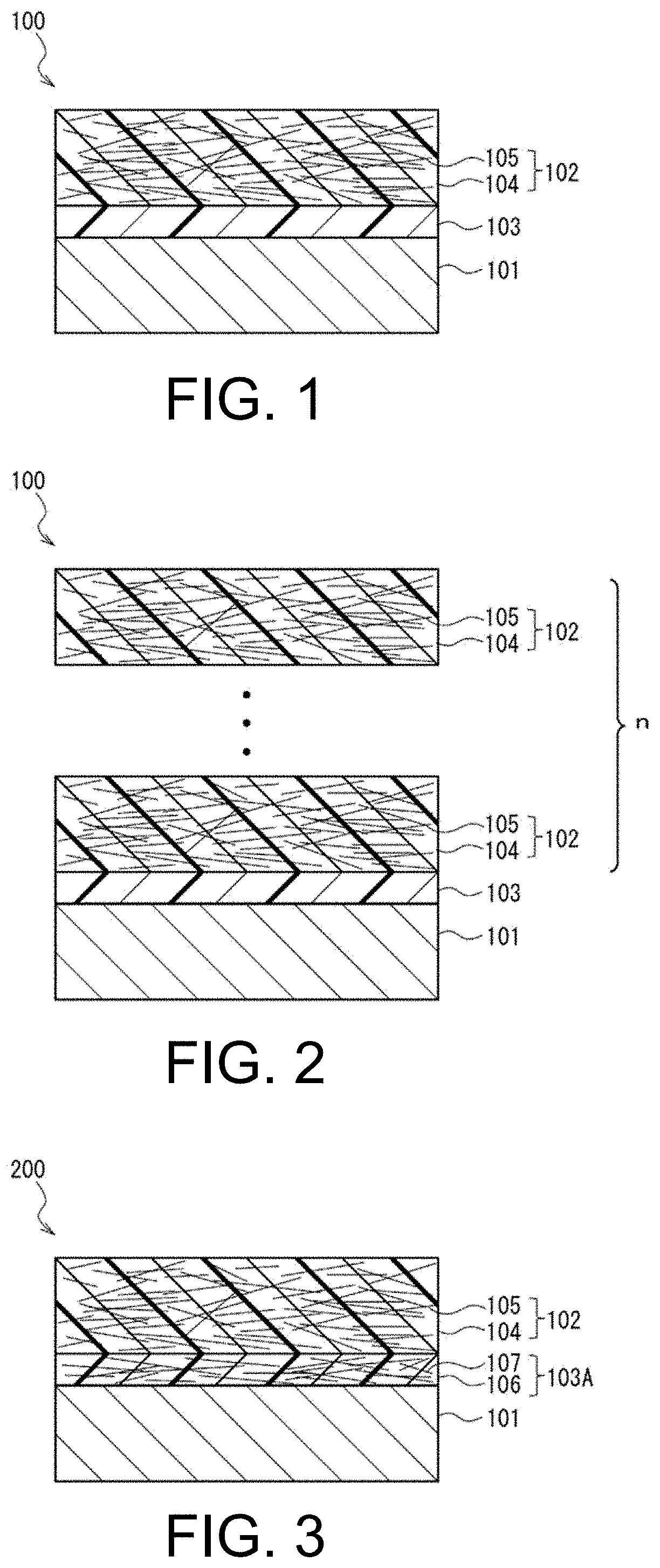
[0048]FIG. 1 and FIG. 2 are schematic views showing a cross-sectional structure of a metal-FRP composite body in a lamination direction as a metal / fiber-reinforced resin material composite body according to a first embodiment of the present invention. As shown in FIG. 1, a metal-FRP composite body 100 includes a metal member 101, an FRP layer 102 as a first fiber-reinforced resin material, and a bonding resin layer 103 interposed between the metal member 101 and the FRP layer 102. As will be described below, the bonding resin layer 103 is a solidified product of a phenoxy resin (A) alone or a cured product of a bonding resin composition containing 50 parts by weight or more of a phenoxy resin (A) in 100 parts by weight of resin components. Here, when simply referred to as a “cured product,” in addition to a cured product in a first cured state which is solidified but it is not crosslinked after the phenoxy resin (A) and the like contained in the bonding resin composition are melted,...

second embodiment

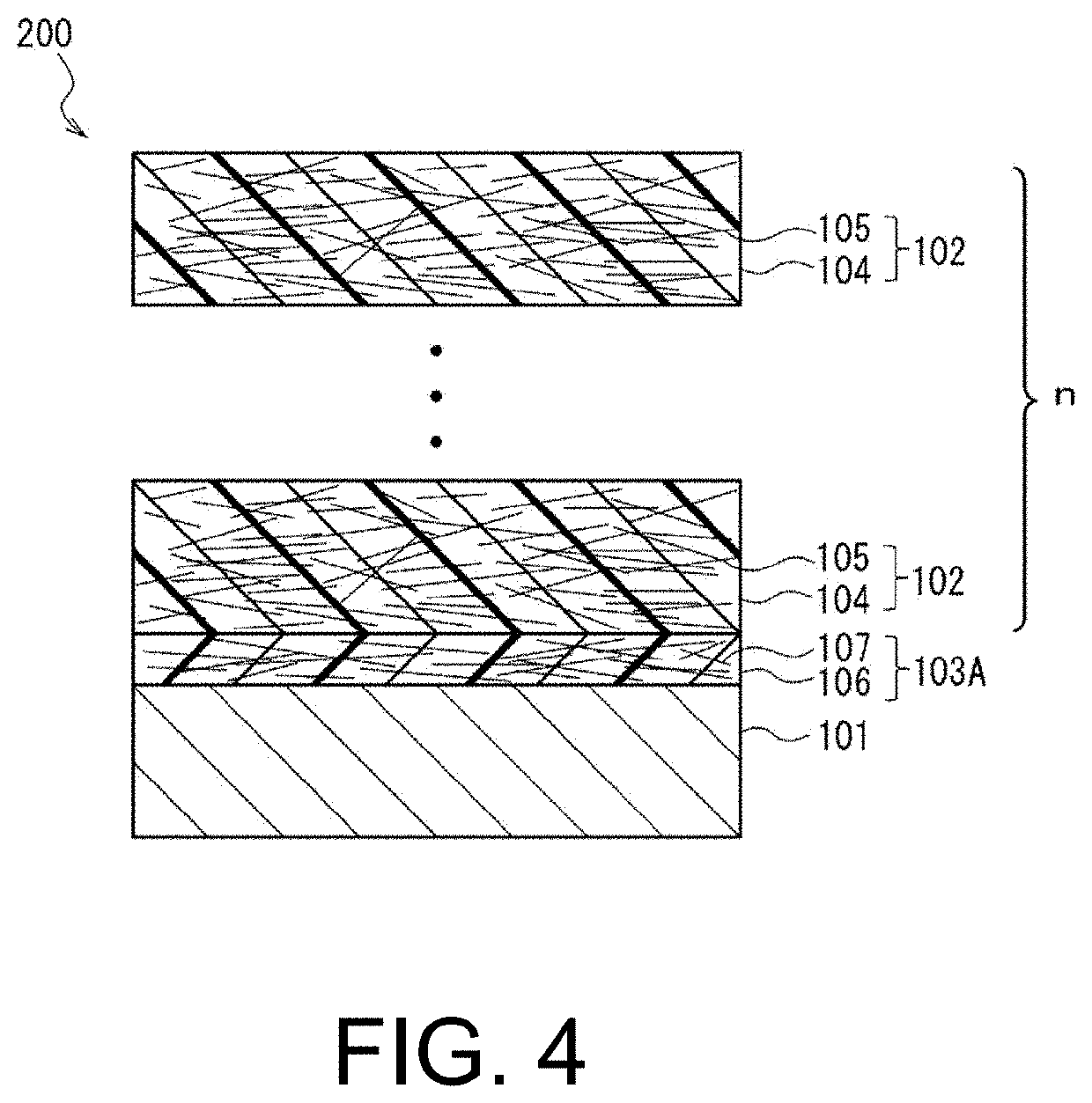
[0052]FIG. 3 and FIG. 4 are schematic views showing a cross-sectional structure of a metal-FRP composite body as a metal / fiber-reinforced resin material composite body according to a second embodiment of the present invention. As shown in FIG. 3, a metal-FRP composite body 200 includes the metal member 101, the FRP layer 102 as a first fiber-reinforced resin material, and a bonding resin layer 103A interposed between the metal member 101 and the FRP layer 102. The bonding resin layer 103A is a second fiber-reinforced resin material including a matrix resin 106 and a reinforced-fiber material 107 contained in and combined with the matrix resin 106. As will be described below, the matrix resin 106 is a solidified product of a phenoxy resin (A) alone or a cured product of a bonding resin composition containing 50 parts by weight or more of a phenoxy resin (A) in 100 parts by weight of resin components. Here, the configuration of the FRP layer 102 is the same as in the first embodiment....

production example 1

Production of a Phenoxy Resin CFRP Prepreg A

[0171]A powder obtained by pulverizing and classifying A-1 and having an average particle size D50 of 80 μm was used as the phenoxy resin (A), carbon fibers (UD material: Pyrofil TR50S 15 L commercially available from Mitsubishi Rayon Co., Ltd.) that were opened and aligned in one direction were used as a base material, and in an electrostatic field, powder coating was performed under conditions of a charge of 70 kV and a spray air pressure of 0.32 MPa. Then, heating and melting were performed in an oven at 170° C. for 1 minute, the resin was thermally fused to form a partially fused structure, and thereby a unidirectional fiber-reinforced phenoxy resin CFRP prepreg A having a thickness of 0.15 mm and a resin proportion (RC) of 48% was produced.


PUM

PropertyMeasurementUnit
Temperatureaaaaaaaaaa
Fractionaaaaaaaaaa
Percent by massaaaaaaaaaa

Abstract

This metal-FRP composite body comprises a metal member, an FRP layer and a bonding resin layer that is interposed between the metal member and the FRP layer. The bonding resin layer is a solidified product of a phenoxy resin (A) by itself, or alternatively, a cured product of a bonding resin composition that contains 50 parts by weight or more of the phenoxy resin (A) in 100 parts by weight of the resin components; and the bonding resin layer firmly bonds the metal member and the FRP layer to each other. The bonding resin composition may additionally contain 5-85 parts by weight of an epoxy resin (B) relative to 100 parts by weight of the phenoxy resin (A), and a crosslinking agent (C) that contains an acid dianhydride.

Description

TECHNICAL FIELD[0001]The present invention relates to, for example, a metal / fiber-reinforced resin material composite body in which a metal member made of a steel material and a resin material are laminated, a method for producing the same, and a bonding sheet.BACKGROUND ART[0002]Fiber-reinforced plastics (FRP) made of reinforced fibers such as glass fibers and carbon fibers, and a matrix resin are widely used across consumer goods and industrial applications because they are lightweight and have excellent mechanical characteristics. In particular, in the automobile industry, since reduction in a vehicle body weight contributes greatly to improving performance and fuel consumption, replacement of steel materials that have mainly been used hitherto with a carbon fiber reinforced plastic (CFRP) or a composite material of a metal member and a CFRP is being actively studied.[0003]When a part or structure in which a CFRP and a metal member are combined is produced, in order to integrate ...

Claims


Application Information

Patent Timeline
IPC IPC(8): B32B7/12B32B15/082B32B15/092B32B15/18B32B15/20B32B27/26B32B27/20B32B27/38B32B27/30
CPCB32B7/12B32B2037/1238B32B15/092B32B15/18B32B15/20B32B27/26B32B27/20B32B27/38B32B27/30B32B2260/021B32B2260/046B32B2250/03B32B2250/05B32B2305/076B32B15/082B29C43/18B29C43/28B29C65/40B32B15/08C08J5/12B32B15/085B32B15/088B32B15/09B32B15/095B32B15/098B32B27/08B32B27/281B32B27/285B32B27/286B32B27/288B32B27/302B32B27/32B32B27/34B32B27/36B32B27/365B32B2262/106B32B2262/10B32B2262/101B32B2262/0269B32B2270/00B32B2307/30B32B2307/546B32B2307/542B32B2605/08C08J5/243B29C66/742C08J5/24B32B37/1284B32B2037/1215B32B2037/1253B32B2311/24B32B2311/30B32B2333/00B32B2363/00
Inventor TAKAHASHI, HIROYUKIANDOH, HIDEKI
Owner NIPPON MICROMETAL
Why Eureka
Try Eureka