
Hydrorefining catalyst, preparation method therefor and use thereof

a technology of hydrofining catalyst and distillate oil, which is applied in the direction of catalyst activation/preparation, metal/metal-oxide/metal-hydroxide catalyst, physical/chemical process catalyst, etc. it can solve the problem that the performance of the catalyst prepared by conventional methods cannot fully meet the requirements, and the pore expansion effect is poor, so as to improve the performance of the catalyst and the reaction space. , the effect of large siz

Active Publication Date: 2021-04-01
CHINA PETROCHEMICAL CORP +1
View PDF0 Cites 2 Cited by
  • Summary
  • Abstract
  • Description
  • Claims
  • Application Information

AI Technical Summary

Benefits of technology

The patent aims to improve the activity of hydrofining catalyst systems in treating low-quality oils by combining two catalysts with different activities. The first catalyst is used to remove impurities from the oil, while the second catalyst is used to ensure better contact between the oil and the first catalyst. The second catalyst also helps to release reaction heat more slowly, reducing coking and improving the reaction's efficiency. This combination of catalysts results in better hydrocracking and overall cleaner oil.

Problems solved by technology

Other methods for the preparation of hydrogenation catalysts include multi-step impregnation methods, coprecipitation methods and the like, but such methods are complicated and thus are not widely used in industries.
However, when used in the treatment of more inferior feedstock oil, the performance of the catalyst prepared by conventional methods still cannot fully meet the requirement.
In the above method using pore-expanding agent, the pore-expanding agent and the pseudo-boehmite are not uniformly mixed, which results in poor pore-expanding effect, and the addition of the pore-expanding agent also increases the cost.
However, this system cannot produce diesel oil with lower sulfur content at relatively lower reaction temperatures.
In order to meet stricter oil quality requirements and treat poorer feedstocks, the desulfurization, denitrification and dearomatization performance of the hydrofining catalyst needs to be further improved, and the existing catalyst grading system cannot meet the requirements.

Method used


Image

  • Hydrorefining catalyst, preparation method therefor and use thereof

Examples


examples

[0561]The present application will be further illustrated with reference to the following examples, which are not intended to limit the scope of the present application.

[0562]In the following Examples I-II series and Comparative Examples I-II series, the hydrodesulfurization performance of the catalyst was determined using a 20 mL high pressure hydrodesulfurization reactor, and catalysts in oxidized state were converted to sulfurized catalysts directly by temperature programmed sulfurizing. The sulfurization conditions include: a sulfurization pressure of 6.4 MPa, use of kerosene containing 2 wt % of CS2 as the sulfurized oil, a volume space velocity of 2 h−1, and a hydrogen-to-oil ratio of 300 v / v. The temperature was kept at 230° C. / h for 6 h, then raised to 360° C. for sulfurization for 8 h, with the temperature raising rate of each stage being 10° C. / h. After sulfurization, the oil was switched to the feedstock oil to carry out a test of the hydrodesulfurization activity, in whi...

example i-1

[0566]This example is provided to illustrate a hydrofining catalyst according to the present application and its preparation.

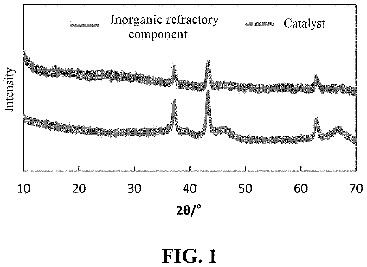
[0567](1) Commercially available white carbon black (purchased from Sinopharm Chemical Reagent Co., Ltd., specific surface area of 220 m2 / g, average pore size of 12.7 nm) and basic cobalt carbonate (purchased from Sinopharm Chemical Reagent Co., Ltd., analytical pure) powder were mixed uniformly, and then calcined at 400° C. for 3 hours to obtain cobalt-containing inorganic refractory powder.

[0568]The amount of basic cobalt carbonate used corresponded to a cobalt content (calculated as cobalt oxide) of the catalyst of 22.0 wt %.

[0569](2) Certain amounts of MoO3 (purchased from Sinopharm Chemical Reagent Co., Ltd., analytically pure), basic cobalt carbonate and propanol (purchased from Sinopharm Chemical Reagent Co., Ltd., analytically pure) were added separately into an aqueous solution containing phosphoric acid (purchased from Sinopharm Chemical Reagent Co.,...

example i-2

[0575]This example is provided to illustrate a hydrofining catalyst according to the present application and its preparation.

[0576](1) Commercially available white carbon black (specific surface area of 220 m2 / g, average pore size of 12.7 nm) and basic nickel carbonate (purchased from Sinopharm Chemical Reagent Co., Ltd., analytically pure) powder were uniformly mixed, and then calcined at 700° C. for 4 hours, to obtain nickel-containing inorganic refractory powder.

[0577]The amount of basic nickel carbonate used corresponded to a nickel content (calculated as nickel oxide) of 15.0 wt % in the catalyst.

[0578](2) Certain amounts of MoO3, basic nickel carbonate and ethylene glycol (purchased from Sinopharm Chemical Reagent Co., Ltd., analytically pure) were added separately into an aqueous solution containing phosphoric acid, stirred while heating until completely dissolved, and then a certain amount of acetic acid (purchased from Sinopharm Chemical Reagent Co., Ltd., analytically pure...


PUM


Abstract

Disclosed is a hydrofining catalyst comprising: an inorganic refractory component comprising a first hydrodesulfurization catalytically active component in a mixture with at least one oxide selected from the group consisting of alumina, silica, magnesia, calcium oxide, zirconia and titania; a second hydrodesulfurization catalytically active component; and an organic component comprising a carboxylic acid and optionally an alcohol. The hydrofining catalyst of the present application shows improved performance in the hydrofining of distillate oils. Also disclosed are a hydrofining catalyst system comprising the hydrofining catalyst, a method for preparing the catalyst and catalyst system, and a process for the hydrofining of distillate oils using the catalyst or catalyst system.

Description

CROSS-REFERENCE TO RELATED APPLICATIONS[0001]The present application is a national stage application of PCT / CN2019 / 081915 (filed Apr. 9, 2019), which claims the priority of Chinese patent application No. 201810317849.X, titled “Hydrofining catalyst, its preparation, application thereof, and process for hydrofining of distillates”, filed before the CNIPA on Apr. 10, 2018, the priority of Chinese patent application No. 201810317845.1, titled “Hydrofining catalyst, its preparation, application thereof, and process for hydrofining of distillates”, filed before the CNIPA on Apr. 10, 2018, the priority of Chinese patent application No. 201810316695.2, titled “Hydrofining catalyst system, its application, preparation thereof, and process for hydrofining of distillates”, filed before the CNIPA on Apr. 10, 2018, and the priority of Chinese patent application No. 201810317848.5, titled “Hydrofining catalyst system, its application, preparation thereof, and process for hydrofining of distillat...

Claims


Application Information

Patent Timeline
Patent Type & Authority Applications(United States)
IPC IPC(8): B01J23/888B01J23/882B01J23/883B01J21/18B01J21/06B01J23/02B01J21/04B01J27/16B01J35/10B01J37/02B01J37/08B01J37/20C10G45/08
CPCB01J23/8885C10G2300/1074B01J23/883B01J23/888B01J21/18B01J21/066B01J23/02B01J21/04B01J27/16B01J35/1061B01J35/1066B01J35/109B01J35/1014B01J35/1019B01J35/1038B01J35/1042B01J37/024B01J37/0205B01J37/0213B01J37/0203B01J37/0236B01J37/088B01J37/20C10G45/08B01J23/882B01J35/66B01J35/615B01J35/647B01J35/69B01J35/613B01J35/633B01J35/635B01J35/651
Inventor CHEN, WENBINZHANG, LELONG, XIANGYUNNIE, HONGLI, MINGFENGLI, DADONGLIU, QINGHEJU, XUEYAN
Owner CHINA PETROCHEMICAL CORP
Learn More